The LTE-based vehicle communication system supports vehicle-to-vehicle (V2V) applications, vehicle-to-infrastructure (V2I) applications, vehicle-to-network (V2N) applications, and vehicle-to-pedestrian (V2P) applications. These applications provide users with various services such as road safety, traffic efficiency improvement, and infotainment.
V2X communication has two operational modes: PC5-based V2X communication and LTE-Uu-based V2X communication.
The LTE-Uu-based operational mode can be either unicast or broadcast. V2X devices can use these two operational modes separately for receiving and sending. For example, a V2X device can receive V2X messages using downlink broadcast over LTE-Uu but send V2X messages without using LTE-Uu. A V2X device can also receive V2X messages via downlink unicast over LTE-Uu.
PC5-based V2X communication reuses the one-to-many ProSe direct communication transmission process, with the PC5-U protocol stack defined in proximity communication used for V2X communication transmission based on the PC5 interface.
V2X communication architecture based on PC5 and LTE-Uu
-
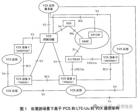
V2X communication architecture based on PC5 and LTE-Uu in non-roaming scenarios
Figure 1 shows the V2X communication architecture based on PC5 and LTE-Uu in non-roaming scenarios.
-
V2X communication architecture based on PC5 and LTE-Uu in roaming scenarios
Figure 2 presents the V2X architecture based on PC5 and LTE-Uu in roaming scenarios, where V2X device A belongs to PLMN A, V2X device B belongs to PLMN B, and V2X device A roams to PLMN B while V2X device B is non-roaming.
The V2X application server can also connect to multiple PLMNs; for example, a V2X application server can connect to the V2X control function entity in PLMN A and also connect to the V2X control function entity in PLMN B.
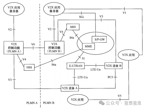
Figure 2 V2X communication architecture based on PC5 and LTE-Uu in roaming scenarios
-
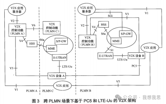
V2X communication architecture based on PC5 and LTE-Uu in cross-PLMN scenarios
Figure 3 shows the V2X architecture based on PC5 and LTE-Uu in cross-PLMN roaming scenarios, where V2X device A belongs to PLMN A, V2X device B belongs to PLMN B, and V2X device A roams to PLMN C while V2X device B is non-roaming.
-
Reference Points
The reference points for the V2X communication architecture based on PC5 and LTE-Uu include the following:
-
V1: Reference point between the V2X application (embedded in the V2X device) and the V2X application server.
-
V2: Reference point between the V2X application server and the V2X control function. The V2X application server can connect to the V2X control functions of multiple PLMNs.
-
V3: Reference point between the V2X device and the V2X control function in the home PLMN, applicable for both PC5-based and LTE-Uu-based V2X communication, with optional support for MBMS in LTE-Uu-based V2X communication.
-
V4: Reference point between the HSS in the operator’s network and the V2X control function.
-
V5: Reference point between V2X applications in different V2X devices.
-
V6: Reference point between V2X control functions in different PLMNs.
-
PC5: Reference point for ProSe direct communication between V2X devices using V2X services.
-
S6a: In the V2X scenario, during the E-UTRAN attachment process, the MME can download V2X communication-related subscription information or notify the MME when the subscription information in the HSS changes.
-
S1-MME: In the V2X scenario, this reference point can transfer V2X service authorization from the MME to the eNodeB.
-
LTE-Uu: Reference point between the UE and E-UTRAN.
V2X communication architecture based on MBMS and LTE-Uu
Figure 4 illustrates the V2X communication architecture based on MBMS and LTE-Uu.
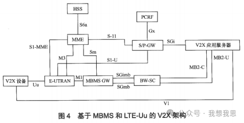
The reference points for this architecture include the following:
-
MB2: Reference point between the V2X application server and the BM-SC.
-
SGmb/SGi-mb/M1/M3: Reference points within the MBMS system for SGmb/SGi-mb/M1/M3.
Security architecture for LTE-based vehicle communication
-
Security protocol architecture for LTE-based vehicle communication
The security of LTE-based vehicle communication includes two parts: bearer security (PC5 security or LTE-Uu security) and V2X application security. Figure 5 describes the V2X security architecture based on PC5, while Figure 6 describes the V2X security architecture based on LTE-Uu.
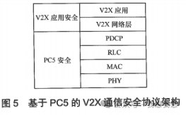
Figure 5 illustrates the V2X communication security protocol architecture based on PC5. The PC5-U protocol stack defined in proximity communication (see 3GPP TS 23.303) is used for V2X communication transmission based on the PC5 interface.
In the V2X communication process based on PC5, the PDCP security of the PC5 interface is disabled.
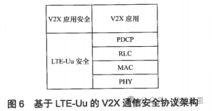
Figure 6 illustrates the V2X communication security protocol architecture based on LTE-Uu, which uses the LTE protocol stack. In the V2X communication process based on LTE-Uu, LTE-Uu security should be supported.
-
Application layer communication security architecture for LTE-based vehicle communication
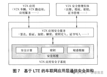
Figure 7 presents the application layer communication security architecture for LTE-based vehicle communication. The functions of each entity in the security subsystem include the following:
-
V2X application security subsystem: Located in the V2X vehicle, V2X roadside units, and V2X service provider’s application service system, responsible for providing communication security functions for V2X applications.
-
V2X application: Located in the V2X vehicle, V2X roadside units, and V2X service provider’s application service system, requiring communication security for V2X applications.
-
V2X security management entity: Responsible for security configuration and security data supply for the V2X application security subsystem, such as registration, authorization, key supply, and certificate issuance.
-
V2X application security service: Located in the V2X application security subsystem, interacts with V2X applications to complete operations such as message signing, verification, encryption, and decryption, and interacts with the V2X security management entity to complete key writing, certificate application, and writing.