Man Tan Jun: Focused on sharingthe most excitingautomotive development technology!
Beauty comes in many forms, including physical beauty, temperament beauty, intellectual beauty, and inner beauty, etc. Often, the most charming combination is a blend of these types!
Cars are similar; a beautiful appearance needs to be paired with good performance, and the combination of both is the most perfect. To achieve good performance, the heart of the car (the engine) is crucial. A good heart needs a smart brain to command, and the ECU, as the brain, is vital.
So today, Man Tan Jun will discuss with you:
The development methods and processes of the automotive brain (ECU)

1Definition of ECU
ECU (Electronic Control Unit): Electronic Control Unit, also known as “vehicle computer” or “on-board computer”. In terms of purpose, it is a microcomputer controller specifically for automobiles. In simple terms, “the ECU is the brain of the car”.

2Composition of ECU
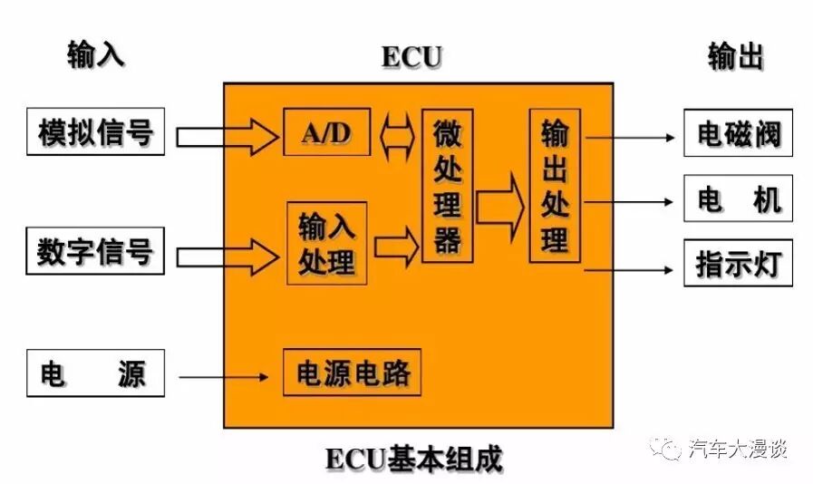
Like a regular computer, the ECU consists of a microprocessor (CPU), memory (ROM, RAM), input/output interfaces (I/O), analog-to-digital converters (A/D), and large-scale integrated circuits for shaping and driving.
3ECU Architecture
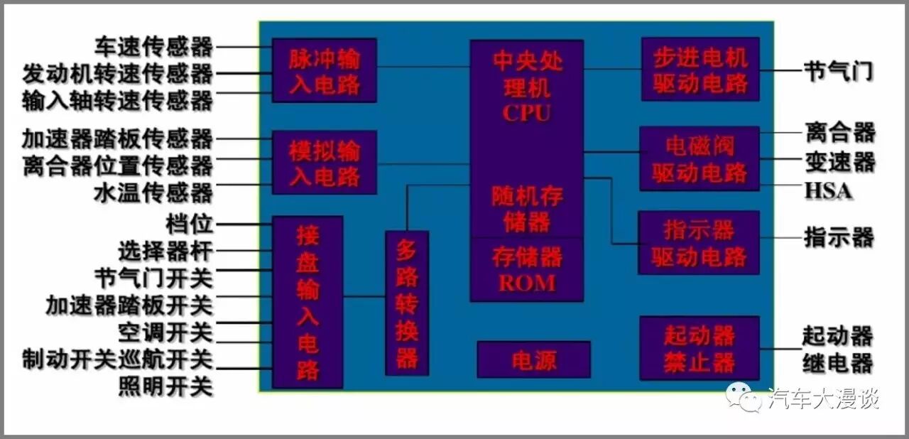
4Working Principle of ECU
The CPU in the ECU is the core part, which has the functions of computation and control. When the engine is running, it collects signals from various sensors, performs calculations, and converts the results into control signals to manage the operation of the controlled objects.
It also controls the memory (ROM/FLASH/EEPROM, RAM), input/output interfaces (I/O), and other external circuits; the programs stored in the ROM are based on precise calculations and extensive experiments. This inherent program continuously compares and calculates the signals collected from various sensors during engine operation. The results of these comparisons and calculations are used to control multiple parameters of the engine, such as ignition timing, air-fuel ratio, idle speed, and exhaust gas recirculation.
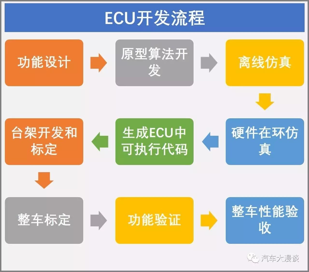
5ECU Development Process
01Prototype ECU – Prototyping Stage
Also known as Prototype PCM (Powertrain Control Module), it represents the early stage of product design. It is mainly used to define the basic structure, design the underlying software, and develop control strategies. The hardware configuration is relatively flexible, and both signal adjustment and output signal driving are initial designs. Generally, it is larger in size and does not consider the requirements of the product stage. In other words, the prototype ECU is used to optimize software quality.
02Development ECU – Calibration Stage
Also known as Calibration ECU, Development PCM, it represents the optimization stage of product design. It requires the software developed on the prototype ECU to be ported to the development ECU, which is mainly used to modify the calibration parameters of the ECU to ensure compatibility with specific engines or vehicles. It is very similar to the product ECU in structure, and many development ECUs are modified based on the product ECU. In the development ECU, only calibration parameters can be modified, but strategies cannot be changed. In other words, the development ECU is used to optimize software quality.
03Product ECU – SOP Stage
Also known as Product PCM, it represents the SOP stage of product design. After prototype design and matching calibration, the final software and calibration parameters are solidified in the memory of the product ECU, which requires further optimization of the product’s electrical performance and electromagnetic compatibility, etc. The content of the product ECU is generally not modifiable.
6V-Cycle Method for ECU Development
01Design Calculation
The purpose of design calculation for engine matching projects is to determine the types and parameters of components such as engines and transmissions based on the performance requirements of the vehicle.
It is divided into the following three methods.
(1) Manual Calculation
This method mainly determines the maximum speed, acceleration capability, and climbing ability of the vehicle under different gear conditions based on the balance diagram of vehicle driving force and resistance, thus evaluating the impact of different transmission ratios on vehicle performance and determining the parameters of the engine and transmission. This method is cumbersome and the results are not very accurate.
(2) Simulation Calculation
Based on the design of vehicle and component models, input performance parameters of components such as engines and transmissions, specify the required driving cycle, and finally calculate the vehicle’s power performance, economy, emission performance, and braking performance. It can display and print various analysis reports and graphical results on the computer, with fast and accurate calculations that reflect the impact of any parameter changes in the vehicle system on overall performance.
(3) Parameter Optimization
This method takes the vehicle’s power performance, economy, emission performance, and braking performance as objective functions, and engine power, vehicle weight, and transmission ratios as optimization variables, seeking the optimal matching combination within a certain range to achieve the best performance-to-price ratio for the vehicle.
02Layout of Engine and Transmission
After completing the engine matching design calculations, based on the initially determined calculation parameters and vehicle layout form, one or more engines and transmissions can be selected from the market, and then corresponding components such as braking, steering, and air conditioning systems can be selected and developed, and trial layouts can be performed in the engine compartment and vehicle body. A CAD digital model of the vehicle and components can also be established to test assembly in a CAD software environment, check for interference, and make adjustments. Once the positions of the main components of the vehicle are determined, subsequent work can proceed.
03Development of Engine Accessory Systems
Typically, automotive engine suppliers only provide the basic engine or engine block, lacking some peripheral accessory systems, so automotive manufacturers need to develop these systems. These accessory systems include: fans and fan clutches, intake and exhaust pipes, air filters, engine oil pumps, engine mounts, power steering pumps, catalytic converters, air conditioning compressors, and fuel supply systems.
04Design and Analysis
(1) CAD Design
In the development process of modern vehicles, CAD software is required to design digital models of vehicles and components.
The main CAD modeling methods include: feature modeling and reverse scanning using coordinate measuring machines.
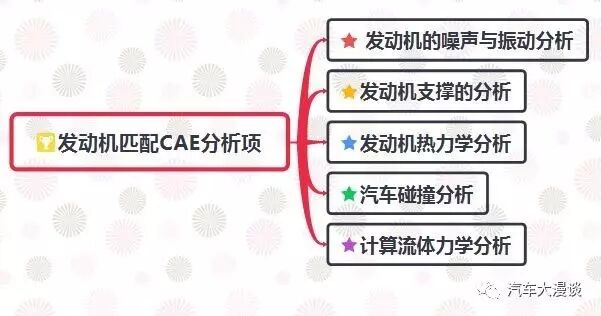
(2) CAE Analysis
CAE analysis projects in engine matching projects include:
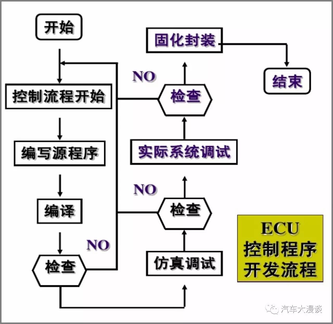
7Design and Development of ECU Control Programs
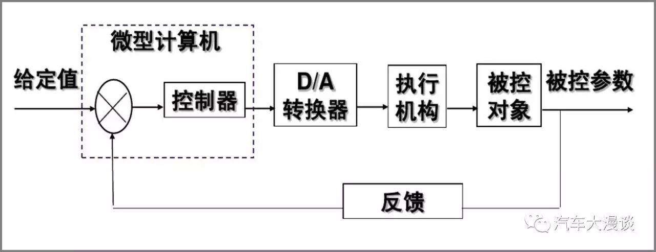
8Control Modes
Open-loop Control and Closed-loop Control
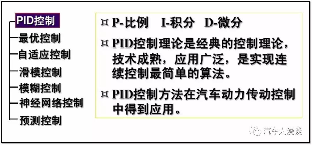
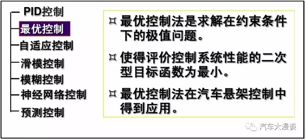
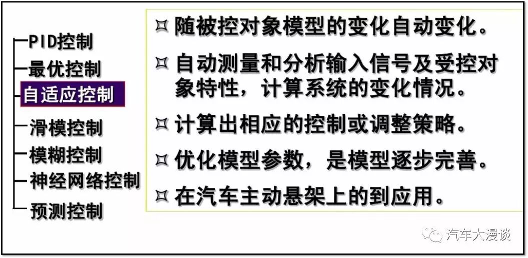
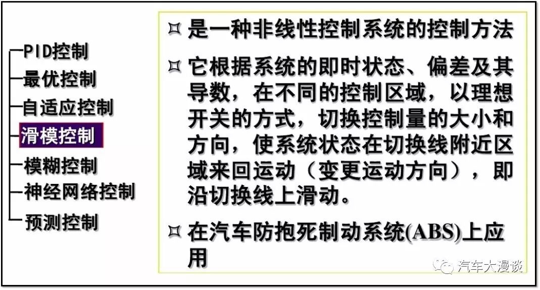
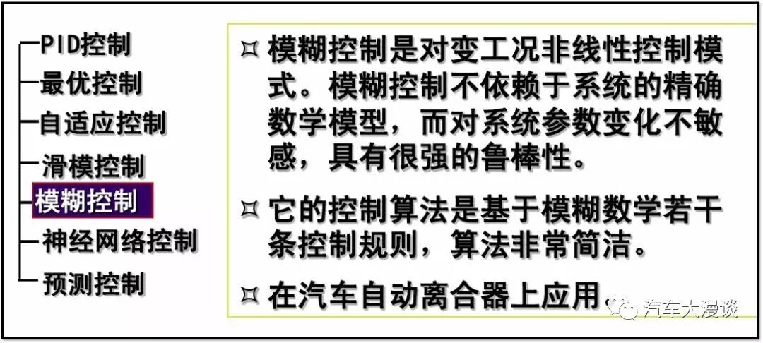
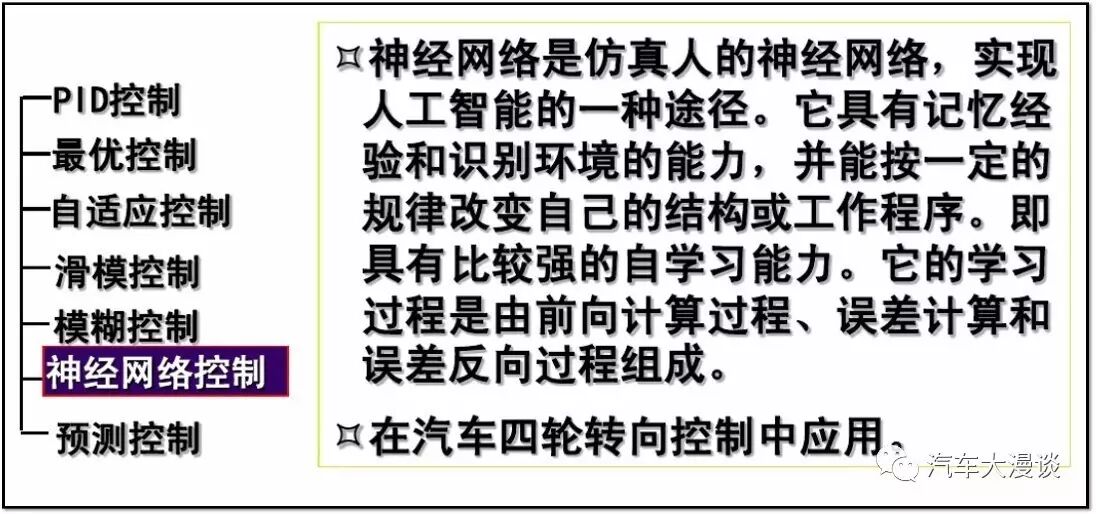
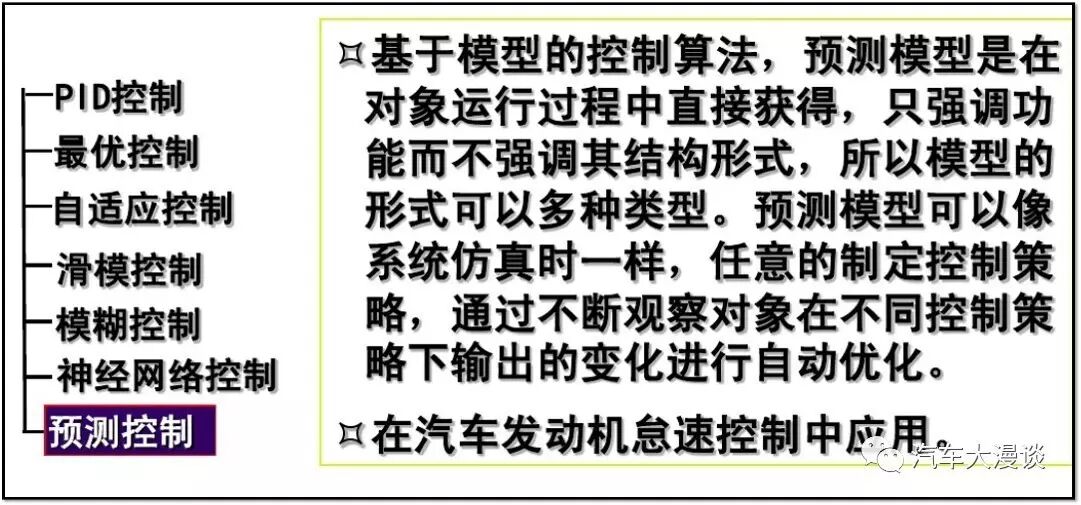
9Control Theory
10ECU Calibration
01Concept of Calibration
Matching calibration is a complex system engineering project. It includes bench tests, controlled environment laboratory tests, calibration calculations based on mathematical models, emission tests, functional validation tests, etc. Throughout the engineering process, various advanced calibration tools (hardware devices and software) must be seamlessly integrated into the calibration system, including ECU communication, software writing, calibration parameter management, online calibration, temperature acquisition systems, and simulated data acquisition systems.
02Components of Calibration System
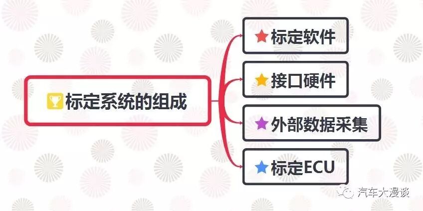
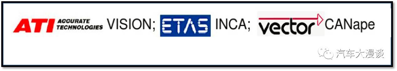
1) Calibration Software
2) Interface Hardware
Kvaser CAN card, VISION Hub, ES1000, ES590, ES591, ES580, CANcardXL, etc.
3) External Data Acquisition
a, Temperature data acquisition module: Thermo-Scan, EDAQ T;
b, Analog data acquisition module: AD-Scan, EDAQ AI;
c, Mixed data acquisition module: DU-Scan;
d, Pressure data acquisition module: Baro-Scan;
e, Wideband oxygen sensors: NTK Lambda Meter, ECM Lambda Meter, LA4 A/F.
4) Calibration ECU
Memory emulators: M5, M6, ETK Emulator, etc.
03ECU Calibration Process
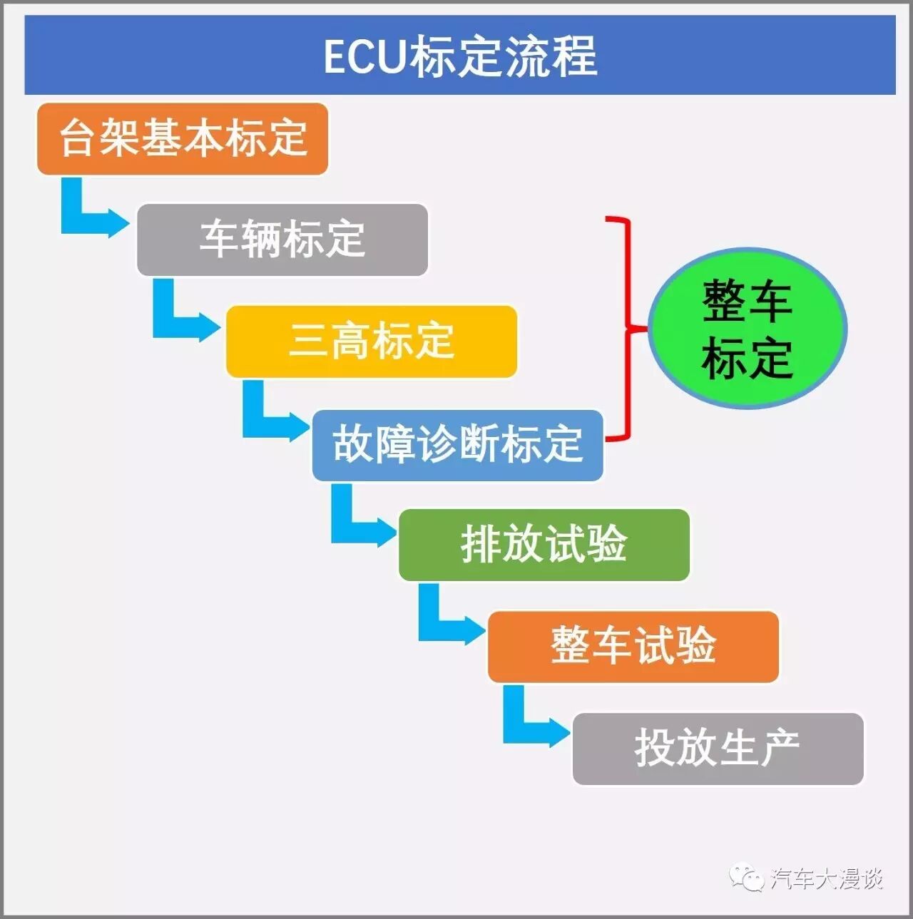
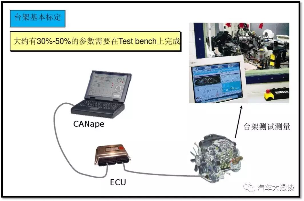
04Basic Calibration on Bench

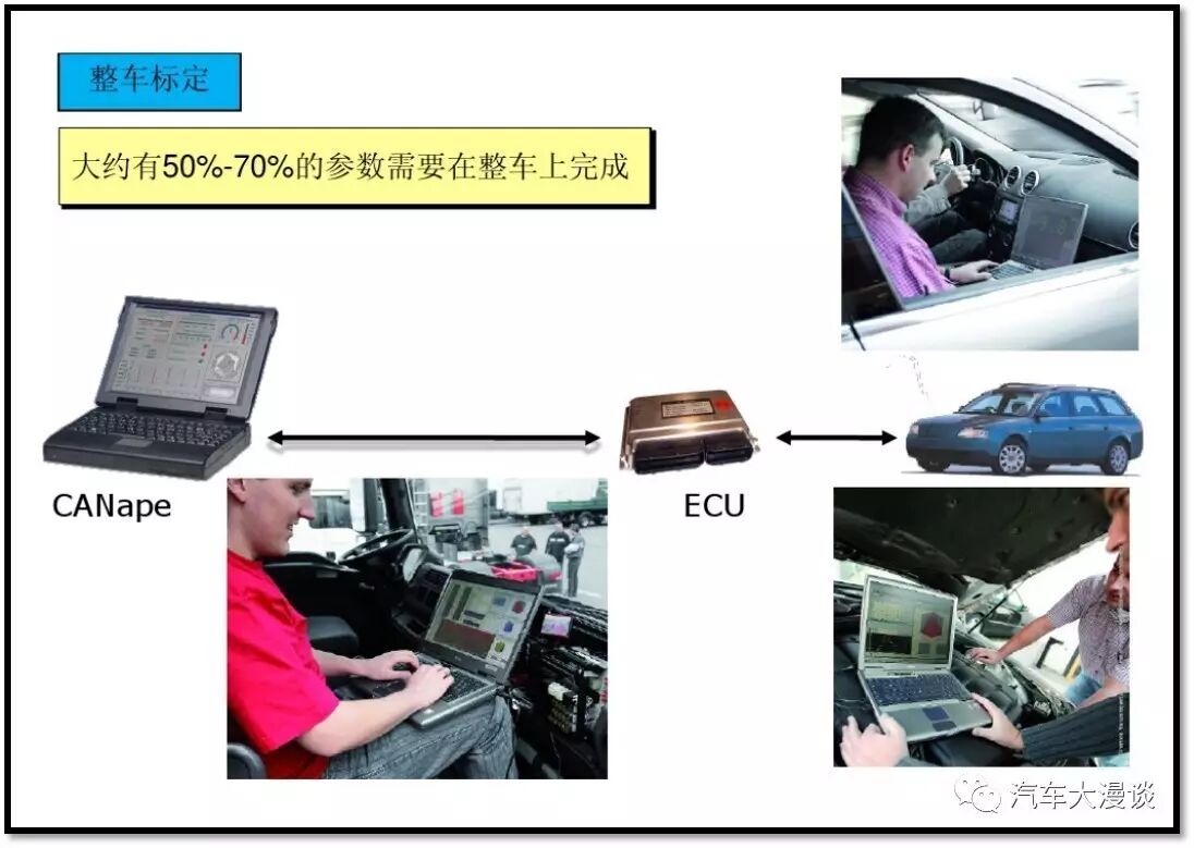
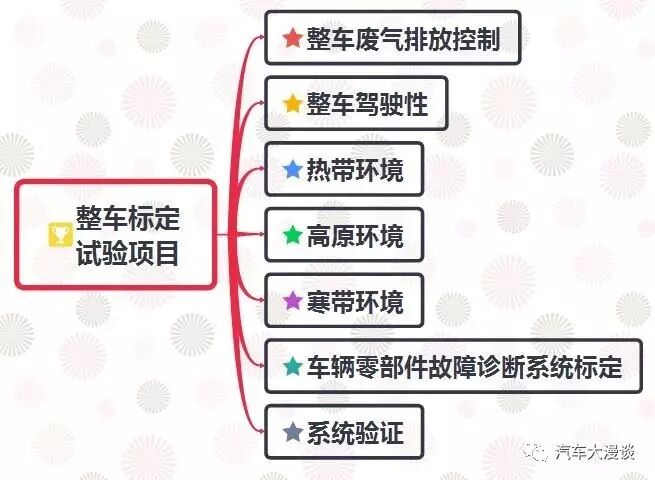
05Whole Vehicle Calibration
06Comparison of Hardware & Software Calibration Solutions
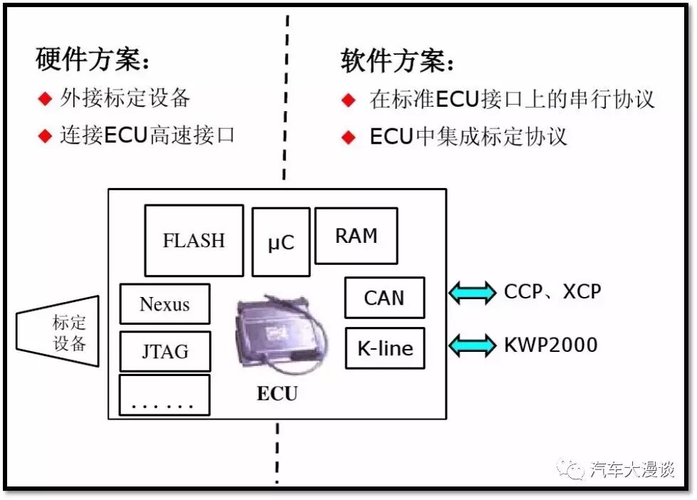
07Hardware Solutions
1) Features:
a) Calibration tools implement calibration protocols and can independently store data with the ECU;
b) Connect to the ECU via high-speed interfaces, providing good performance.
2) Advantages:
a) Good performance, fast speed;
b) No need to integrate calibration protocols within the ECU.
3) Disadvantages:
a) Structural modifications are required for the ECU;
b) Installation position design must be considered.
08Software Solutions
1) Features:
a) Necessary protocol driver code;
b) Read RAM via protocols;
c) Requires additional ECU resources.
2) Advantages:
Data is transmitted via the bus, and no structural changes to the ECU are needed.
3) Disadvantages:
a) Lower performance, occupying some ECU resources;
b) Requires calibration protocol stack.
09Serial Calibration
1) ME = Memory Emulation;
2) Parallel calibration method – backpack;
3) Achieved by modifying hardware, using an external large memory to simulate the PCM’s internal Flash EPROM, connected to the external data bus of the microprocessor;
4) Customization is required based on the type of external bus;
5) Two functions:
a) Calibration – i.e., timely modification of parameters in the ECU;
b) Data acquisition – i.e., measurement of data in the ECU.
6) During calibration, calibration parameters are shadow-mapped to the ME’s emulator RAM;
7) Can simulate only “calibration data” or simultaneously simulate “application program + calibration data”.
10CCP Parallel Calibration
1) CCP = CAN Calibration Protocol
2) Serial calibration method, implemented via software;
3) Mainly uses the ECU’s own RAM or additional RAM space;
4) Two functions:
a) Calibration – i.e., modification of parameters in the ECU;
b) Data acquisition – i.e., measurement of data in the ECU.
5) During calibration, calibration parameters are stored in the extended RAM of the ECU;
6) Can operate on “calibration data” only or apply “program code + calibration data”.
11Introduction to Typical Calibration Tool – CANape
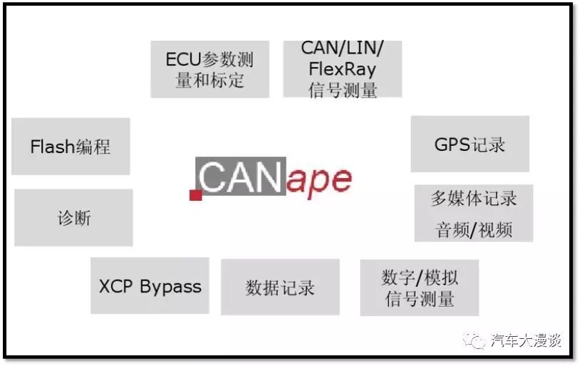
10CANape
01Basic Functions of CANape
1) Synchronously collects and displays internal ECU signals (via CCP/XCP), CAN, LIN, FlexRay bus signals, and signals from external measurement devices;
2) Online calibration via CCP/XCP and real-time stimulation via XCP;
3) Offline calibration;
4) Quickly and safely writes binary files and parameter sets to Flash (Flash programming);
5) Seamless integration of KWP2000 and UDS diagnostic functions;
6) Powerful calibration data management, parameter set comparison, and merging functions;
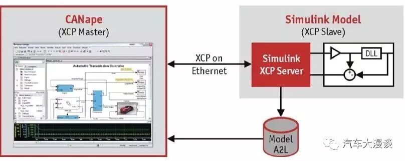
7) Uses integrated MATLAB/Simulink models for calculations during measurement, offline analysis, or bypassing processes;
8) ASAM MCD3 measurement and calibration automation interface;
9) Synchronously collects environmental data such as video, audio, GPS, and external measurement devices along with ECU measurement data;
10) Automatically executes user input sequences and processes measurement values and signals using an integrated programming language.
02Special Functions of CANape
1) Monitors CAN, FlexRay, and LIN buses (1.3, 2.0, and Cooling Bus);
2) Measures and calibrates via CAN, FlexRay, LIN (1.3, 2.0, and Cooling Bus), USB, Ethernet, and serial ports;
3) Supports ODX2.0 standard for flash and diagnostic data;
4) Automatic Flash programming process controlled by ODX-F files;
5) Provides reliable and synchronized evaluation of driving conditions through audio and video recording without keyboard input;
6) Uses an independent database tool eASEE.cdm for reliable server-based management of calibration data;
7) Optional plugins can extend CANape’s functionality to display GPS vehicle location, add ASAM MCD3 interfaces, observe OSEK operating systems, and subjectively evaluate target recognition algorithms during the development of driver assistance systems.
03Measurement Data Acquisition
Through CCP and XCP measurement and calibration protocols, CANape can synchronously acquire measurement parameters from within the ECU. Synchronization means that the allocation of measurement data sampling points can be precise to a task cycle of the ECU. The ECU’s measurement data is stored synchronously with other measurement data (from CAN, LIN, or FlexRay buses, GPS, audio, video, or other measurement devices) and displayed through various means.
CANape’s measurement data acquisition features include:
1) Can be graphically displayed using various window types and user-defined panels;
2) Analyze bus communication in tracking windows;
3) Combine real variables from different sources and calculate virtual signals online using built-in scripting language or MATLAB/Simulink models;
4) Use various triggers for data recording, including pre-trigger and post-trigger times (including audio and video);
5) Synchronously acquire scalar values and arrays;
6) Configurable data loggers CANlog and CANcaseXL log for CCP and XCP measurements;
7) Data measurement rates can exceed 1MBit/s (depending on the interface used).
04Measurement Data Evaluation
CANape provides numerous functions for conveniently processing and evaluating previous measurement data:
1) Script-driven and automated evaluation of measurement files;
2) Arithmetic evaluation using integrated programming language or MATLAB/Simulink models;
3) Signals can be displayed in time or XY views;
4) Use zoom, search, and measurement ruler functions to observe signal responses;
5) Input comments and macros for offline analysis;
6) Import and export measurement files in different formats;
7) Export synchronized video clips from measurement files;
8) Conveniently manage measurement files using the measurement file manager.
05Calibration Data Management
CANape uses integrated CDM Studio to manage parameter sets in various file formats. Parameter sets contain values of parameters specified in the ECU description files. CANape provides the following calibration data management functions:
1) Parameter sets are stored symbolically in address-independent parameter set files, making parameter set processing independent of the ECU program that created them;
2) Visual display and editing of parameter set contents;
3) Multiple parameter sets can be opened simultaneously for comparison, merging, and editing;
4) Flash programming of parameter sets;
5) Supports XML-based PaCo format, allowing for the storage of sufficient metadata for each parameter value, such as maturity, history, editor, date, and comments;
6) Interpolation of copied characteristic curves and maps with varying numbers of interpolation points;
7) Signal selection and display according to desired filtering depth;
8) Import and export configurations.
06Diagnostic Functions
In addition to diagnosing individual ECUs, CANape also provides a method for viewing vehicle functions through functional addressing via the ECU. CANape allows symbolic access to diagnostic data and diagnostic services. The description files can be in ODX 2.0 format or Vector CDD format. If there is no dedicated diagnostic description file, the provided generic UDS and KWP2000 files can be used for symbolic access to functions and raw data.
As a diagnostic tester, CANape provides the following functions:
1) Select, parameterize, and execute diagnostic functions from the diagnostic console;
2) Display and process fault memory in a dedicated window, symbolic display window for DTCs and environmental parameters;
3) Script-driven, ODX-controlled flash programming;
4) Comprehensive analysis of diagnostic communication in tracking windows: (CAN) messages, transmission protocol data, protocol data, and diagnostic data;
5) Address-oriented access to ECU data defined by A2L through diagnostic functions;
6) Visual display of diagnostic function flow in chronological order;
7) Implementation of automated diagnostic sequences via scripts;
8) User-friendly automated interface for accessing diagnostic services;
9) Functional addressing, such as querying multiple ECUs’ IDs using a diagnostic function.
07Supported Measurement Devices
The following measurement devices can be interconnected with CANape:
1) Vector VS6×× measurement modules and compatible components from ETAS for acquiring analog voltage and temperature signals;
2) Vector IOcab8444opto hardware interface for acquiring and outputting analog and digital signals;
3) Vector CANextender;
4) Firewire modules from Ipetronik;
5) Analog and digital measurement hardware from NI;
6) Thermal measurement modules from Solartron;
7) All measurement data acquisition devices connected to the PC via CAN, such as CSM, IMC, and devices from Ipetronik;
8) Vector VX1000 calibration devices.
ECUs are crucial in engine management and are also key to the entire vehicle, making them an important branch in development. With the advancement of technology, they will continue to improve!
Note: Some images and information in this article are sourced from the internet,
compiled by Man Tan Jun based on experience, for learning and communication purposes only!
Click the bottom left toread the original text, reading “Automotive Development: Methods and Processes for Whole Vehicle Wiring Harness Design and Development!”


Scan to add Man Tan Jun’s WeChat:
Autotechstudy, let’s discuss automotive technology together!