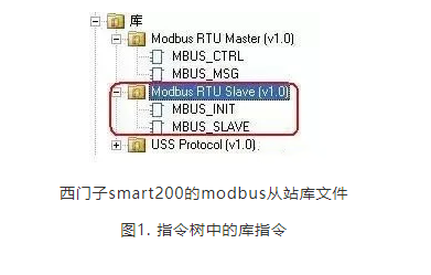
1.Check the Micro/WIN SMART Modbus RTU Slave instruction library (Figure 1), which should include the MBUS_INIT and MBUS_SLAVE subprograms.
2.Use SM0.1 to call the MBUS_INIT subprogram for initialization, and use SM0.0 to call MBUS_SLAVE, specifying the corresponding parameters. Detailed explanations of the parameters can be found in the local variable table of the subprogram;
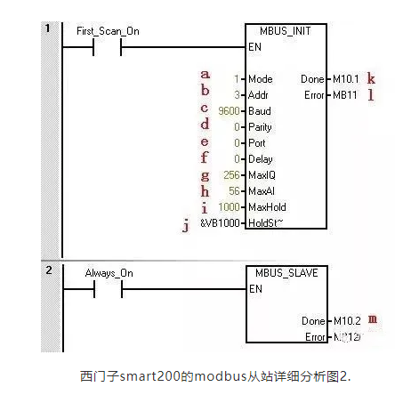
The meanings of the parameters in the figure are as follows:
a.Mode selection: Start/Stop Modbus, 1=Start; 0=Stop
b.Slave Address: Modbus slave address, value range 1~247
c.Baud Rate: Options are 1200, 2400, 4800, 9600, 19200, 38400, 57600, 115200
d.Parity: 0=No parity; 1=Odd parity; 2=Even parity
e.Port: 0=Integrated RS-485 in CPU, 1=RS-485 or RS-232 on optional signal board.
f.Delay: Additional delay between characters, default value is 0
g.Max I/Q Bits: Maximum number of I/O points participating in communication, S7-200 SMART I/O image area is 256/256 (currently can connect up to 4 expansion modules, thus max I/O points are 188/188)
h.Max AI Words: Maximum number of AI channels participating in communication, up to 56
i.Max Holding Register Area: Participating communication V storage area (VW)
j.Starting Address of Holding Register Area: Specified using &VBx (indirect addressing)
k.Initialization Completion Flag: Set to 1 after successful initialization
l.Initialization Error Code
m.Modbus Execution: Set to 1 during communication, 0 when no Modbus communication activity.
n.Error Code: 0=No error
3.Allocate library instruction data area in the CPU’s V data area (Library Memory). The Modbus Slave instruction library requires a global V storage area of 781 bytes. Calling the STEP 7 – Micro/WIN SMART Instruction Library (instruction library) requires allocating a library instruction data area (Library Memory). The library instruction data area is the variable storage space needed by the subprograms and interrupt programs of the corresponding library. If the library instruction data area is not allocated during programming, many identical errors will occur during compilation.
Steps:
1) In the instruction tree of Project, right-click on Program Block, and select Library Memory from the pop-up shortcut menu.
“Library Memory” button 2 sets the library instruction data area in the pop-up tab
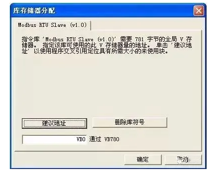
By default, it starts from VB0, but ensure that the storage address range used by this memory does not overlap with the addresses used by other programs. The “Suggest Address” button can also automatically allocate. If necessary, use the master station software for testing
Note: The holding register area specified by the subprogram parameters HoldStart and MaxHold is allocated in the V data storage area of the S7-200 SMART CPU, and this data area cannot overlap with the library instruction data area. Otherwise, errors will occur during runtime, and communication will not function properly. Note that the holding register area in Modbus is addressed by “words”, meaning MaxHold specifies VW, not the number of VB.
In the example of Figure 2, the Modbus holding register area starts from VB1000 (HoldStart = VB1000), and the holding register is 1000 words (MaxHold = 1000). Since the holding register is counted in words (two bytes), this communication buffer actually occupies VB1000 to VB2999, totaling 2000 bytes. Therefore, when allocating the library instruction reserved data area, at least avoid the VB1000 to VB2999 range.
Note: The size of the V storage area of the CPU you choose! The size of the V data storage area varies by CPU model. Select the size of the Modbus holding register area according to your needs.
After compiling and downloading the project containing the Modbus RTU Slave instruction library into the CPU, running some Modbus testing software on the programming computer (PG/PC) can verify whether the S7-200 SMART CPU’s Modbus RTU communication is normal, which is useful for troubleshooting. The testing software connects to the CPU via the computer’s serial port (RS-232) and the PC/PPI cable. If necessary, the PC/PPI cable must be set to free port communication mode.
Siemens Smart 200 Modbus Communication Project Example
The Modbus RTU Slave address corresponds to the S7-200 SMART address: Modbus addresses always appear in the form of 00001, 30004, etc. The correspondence between the internal data storage area of the S7-200 SMART CPU and the four types of Modbus addresses (0, 1, 3, 4) is as follows:
Where T is the starting address of the buffer in the S7-200 SMART CPU, i.e., HoldStart.
If the V storage area address in the S7-200 SMART CPU is known, the formula for calculating the Modbus address is as follows:
Modbus Address = 40000 + (T/2+1); T is an even number
Modbus RTU Slave Instruction Library Supported Modbus Function Codes
The Modbus RTU Slave Instruction Library supports specific Modbus functions.The master station using this instruction library must follow the requirements of this instruction library.
Both communication parties must support one of the modes mentioned above simultaneously. Modbus is a single-master master/slave communication mode. There can only be one master station on the Modbus network, and the master station has no address, while the slave address range is 0 – 247, where 0 is the broadcast address, and the actual slave address range is 1 – 247.
Modbus communication standard protocol can be propagated through various transmission methods, such as RS232C, RS485, fiber optics, radio, etc. The RS485 half-duplex communication implemented on the S7-200 CPU communication port uses the free port function of the S7-200 SMART.
Disclaimer: This article is reprinted from the internet, and the copyright belongs to the original author. If there are any copyright issues, please contact us in time to delete it, thank you!
2022 Electrician Beginner Exam Question Bank Complete (Includes Answers)
Three essential tools for electrical workers, easily accessible via WeChat!
【Collection】 The “Path” of a veteran electrician, the secret to earning over ten thousand a month!
The five major electrical drawing software (CAD, Eplan, CADe_simu…), which one do you pick?
The latest electrical version CAD drawing software, with a super detailed installation tutorial!
The latest electrical drawing software EPLAN, with a super detailed installation tutorial!
Common issues faced by beginners using S7-200 SMART programming software (with download links)
Comprehensive electrical calculation EXCEL sheets, automatically generated! Electrical calculations made easy!
Bluetooth headphones, electrical/PLC beginner books are yours to claim? Come and get your electrical gifts!
Basic skills in PLC programming: Ladder diagrams and control circuits (with 1164 practical cases of Mitsubishi PLC)
Still can’t understand electrical diagrams? Grab the basics of electrical drawing and simulation software to quickly get started!
12 free electrician video courses, 10GB software/e-book materials, and 30 days of free electrician live courses are being given away!