
Here we continue to share knowledge about MODBUS communication between the HMI and the variable frequency drive (VFD).Previously, we discussed the two steps required to achieve communication between the HMI and the VFD:
(1) Selection of communication driver in the HMI
(2) Establishment of variables in the HMI
Today, we will continue to share some tips on layout design in the HMI and configuration.
3. Layout and Tips for HMI Screens
When configuring a Siemens HMI, you can copy some images into the HMI. For instance, if you write names using text in the Siemens HMI, the font is quite limited, and you cannot choose more fonts. This applies to buttons and numeric input/output displays, which are quite monotonous if solely relying on the components provided by the HMI software. In this case, we can create designs externally and then take screenshots to copy into the HMI screen, such as taking screenshots from PPT. As shown in the following image:
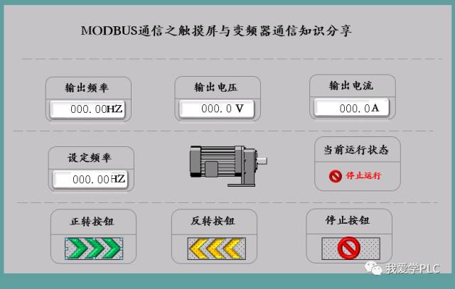
The entire content of this screen is designed in PPT, and then a screenshot is placed here. When taking the screenshot, pay attention to the consistency in size.
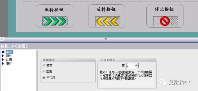
After designing the screen, configure the corresponding buttons, numeric displays, and status displays as shown in the above image. Place an invisible button over each externally designed button and configure it as shown in the image:
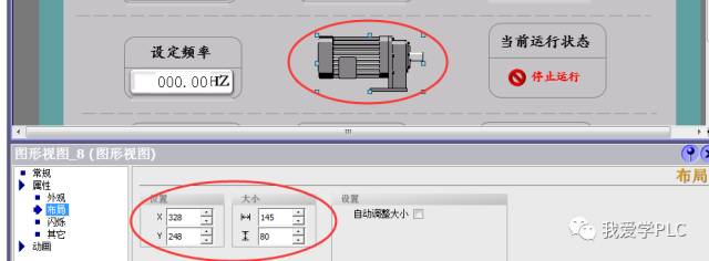
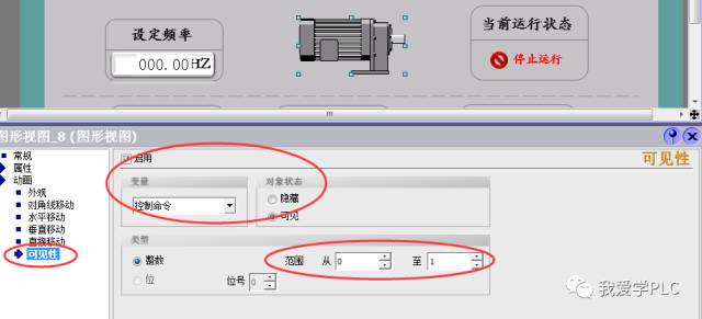
Numeric displays can be processed in the same manner. When selecting styles, choose ‘no style’ so that the numeric display area will not have borders. For motors, you can select motors of different colors and configure the display of different images based on the value in the dialog properties. When layering images, ensure that you set the same size and position for stacking. For example, three motors of different colors are overlaid here to represent different statuses of the motor:
Based on the different numbers in the variables, different motors are displayed, as shown in the image:
4. Variable Connections and Configurations in the Screen
In this screen, in addition to the state display configurations mentioned above, the main task is to configure the forward and reverse operation of the motor, the stop button, and the input and output of frequency, voltage, and current displays.
(1) Button Configuration
Controlling the operation of the VFD requires clicking a button. Upon clicking, the corresponding command code value needs to be written into the corresponding Modbus information register address of the VFD. Therefore, the operation of the button is not merely a position control. When selecting event functions, we cannot choose to edit bit functions like in PLC control; instead, we should select input value functions, as shown in the following image:
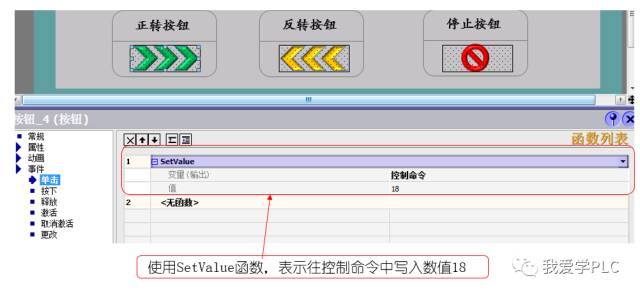
Similarly, for the reverse and stop buttons, we only need to write different values into the control command.
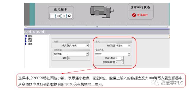
(2) Frequency and Voltage/Current Input Display Configuration.
Taking input frequency as an example, in a previous article, we noted that the input frequency has two decimal places, meaning the frequency resolution is 0.01HZ. Therefore, if an input value of 3000 is entered, the input frequency will be 30.00HZ. Do we need to perform calculations on the touch screen? Should we divide the input number by 100? Here, we can avoid calculations; we only need to move the decimal point. As shown in the image:
We hope this sharing inspires everyone. Please correct any inaccuracies. Thank you!!!
Recommended Articles
[Detailed Steps] Networking Connection Method for Two S7-1200 PLCs and One HMI Device
How to Plan PLC Programming Variables for Easy Memorization?
[Free] Project Case – Ultrasonic Cleaning Machine Development Video Course
Selected Practical Electrical Knowledge – 100 Cases, Enough for You to Learn for a While!
A One-Stop Guide to Getting Started | Using Schneider TM4ES4 Ethernet Switch Module
PLC Programming Examples | Step-by-Step Guide to Designing PLC Control for Motor Start/Stop/Reverse Control System~
First Print of 1000 Copies Sold Out Instantly, the Most Popular Siemens Reference Book is Here!