Introduction
Modbus was developed by MODICON in 1979 and is a standard for industrial fieldbus protocols. In 1996, Schneider Electric launched the Modbus protocol based on Ethernet TCP/IP: ModbusTCP.
The Modbus protocol is an application layer messaging protocol that includes three types of messages: ASCII, RTU, and TCP.
The standard Modbus protocol physical layer interfaces include RS232, RS422, RS485, and Ethernet interfaces, using a master/slave communication method.
Modbus TCP Data Frame
The data frame of ModbusTCP can be divided into two parts: MBAP + PDU.
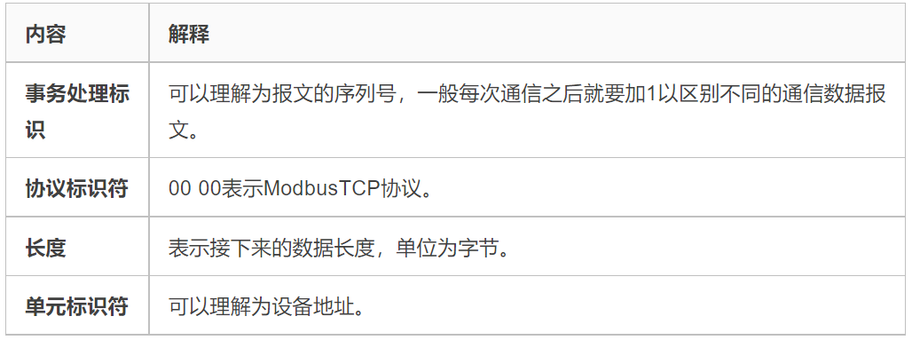
Message Header MBAP
MBAP is the message header, with a length of 7 bytes, composed as follows:

Frame Structure PDU
PDU consists of Function Code + Data. The function code is 1 byte, and the data length is variable, determined by the specific function.
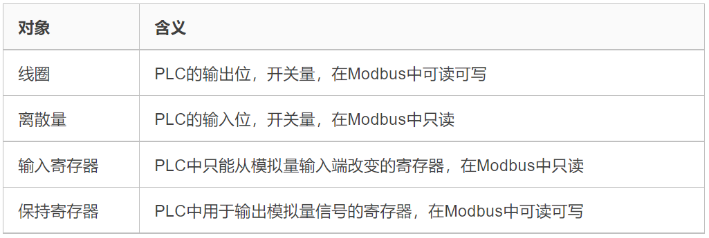
Function Code
There are four types of Modbus operation objects: coils, discrete inputs, holding registers, and input registers.
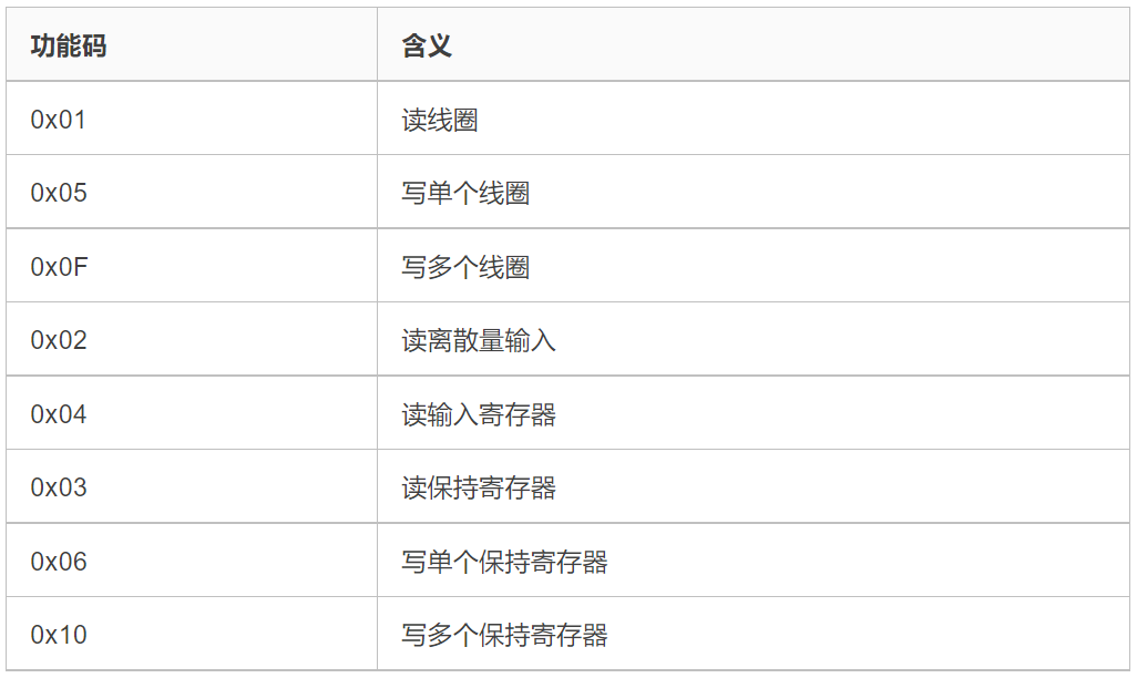
According to different objects, the function codes of Modbus are:
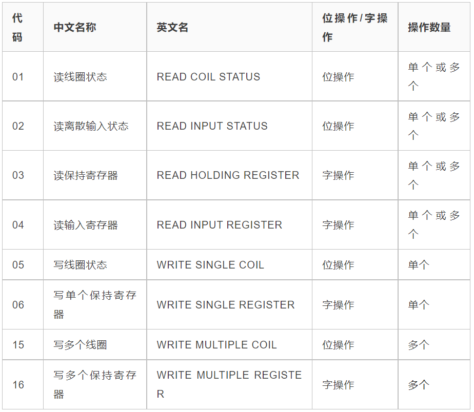
More detailed explanation table:
PDU Detailed Structure
0x01: Read Coils
Read 1 to 2000 consecutive coil statuses from the slave, ON=1, OFF=0.
-
Request: MBAP Function Code Start Address H Start Address L Quantity H Quantity L (Total 12 bytes)
-
Response: MBAP Function Code Data Length Data (1-bit data for one address)
-
For example: In Slave 0x01, read coil data starting from address 0x0002, read 0x0008 bits 00 01 00 00 00 06 01 01 00 02 00 08
-
Response: Data length is 0x01 byte, data is 0x01, the first coil is ON, the rest are OFF 00 01 00 00 00 04 01 01 01 01
0x05: Write Single Coil
Write a single output in the slave as ON or OFF, 0xFF00 request output to be ON, 0x000 request output to be OFF.
-
Request: MBAP Function Code Output Address H Output Address L Output Value H Output Value L (Total 12 bytes)
-
Response: MBAP Function Code Output Address H Output Address L Output Value H Output Value L (Total 12 bytes)
-
For example: Set the coil at address 0x0003 to ON 00 01 00 00 00 06 01 05 00 03 FF 00
-
Response: Write successful 00 01 00 00 00 06 01 05 00 03 FF 00
0x0F: Write Multiple Coils
Force each coil in a sequence in a slave to be ON or OFF, bits set to 1 in the data field request corresponding output bits to be ON, bits set to 0 request corresponding output bits to be OFF.
-
Request: MBAP Function Code Start Address H Start Address L Output Quantity H Output Quantity L Byte Length Output Value H Output Value L
-
Response: MBAP Function Code Start Address H Start Address L Output Quantity H Output Quantity L
0x02: Read Discrete Inputs
Read 1 to 2000 consecutive discrete input statuses from a slave.
-
Request: MBAP Function Code Start Address H Start Address L Quantity H Quantity L (Total 12 bytes)
-
Response: MBAP Function Code Data Length Data (Length: 9+ceil(Quantity/8))
-
For example: Read 0x0012 discrete inputs starting from address 0x0000 00 01 00 00 00 06 01 02 00 00 00 12
-
Response: Data length is 0x03 bytes, data is 0x01 04 00, indicating the first discrete input and the 11th discrete input are ON, the rest are OFF 00 01 00 00 00 06 01 02 03 01 04 00
0x04: Read Input Registers
Read 1 to 2000 consecutive input registers from a remote device.
-
Request: MBAP Function Code Start Address H Start Address L Register Quantity H Register Quantity L (Total 12 bytes)
-
Response: MBAP Function Code Data Length Register Data (Length: 9+Register Quantity×2)
-
For example: Read register data starting from address 0x0002, quantity 0x0005 00 01 00 00 00 06 01 04 00 02 00 05
-
Response: Data length is 0x0A, the first register data is 0x0c, the rest are 0x0000 01 00 00 00 0D 01 04 0A 00 0C 00 00 00 00 00 00 00 00
0x03: Read Holding Registers
Read the contents of a continuous block of holding registers from a remote device.
-
Request: MBAP Function Code Start Address H Start Address L Register Quantity H Register Quantity L (Total 12 bytes)
-
Response: MBAP Function Code Data Length Register Data (Length: 9+Register Quantity×2)
-
For example: Starting address is 0x0000, register quantity is 0x0003 00 01 00 00 00 06 01 03 00 00 00 03
-
Response: Data length is 0x06, the first register data is 0x21, the rest are 0x0000 01 00 00 00 09 01 03 06 00 21 00 00 00 00
0x06: Write Single Holding Register
Write a holding register in a remote device.
-
Request: MBAP Function Code Register Address H Register Address L Register Value H Register Value L (Total 12 bytes)
-
Response: MBAP Function Code Register Address H Register Address L Register Value H Register Value L (Total 12 bytes)
-
For example: Write data 0x000A to register at address 0x0000 00 01 00 00 00 06 01 06 00 00 00 0A
-
Response: Write successful 00 01 00 00 00 06 01 06 00 00 00 0A
0x10: Write Multiple Holding Registers
Write a continuous block of registers (1 to 123 registers) in a remote device.
-
Request: MBAP Function Code Start Address H Start Address L Register Quantity H Register Quantity L Byte Length Register Values (13+Register Quantity×2)
-
Response: MBAP Function Code Start Address H Start Address L Register Quantity H Register Quantity L (Total 12 bytes)
-
For example: Write data to registers starting from address 0x0000, quantity 0x0001, data length is 0x02, data is 0x000F 00 01 00 00 00 09 01 10 00 00 00 01 02 00 0F
-
Response: Write successful 00 01 00 00 00 06 01 10 00 00 00 01
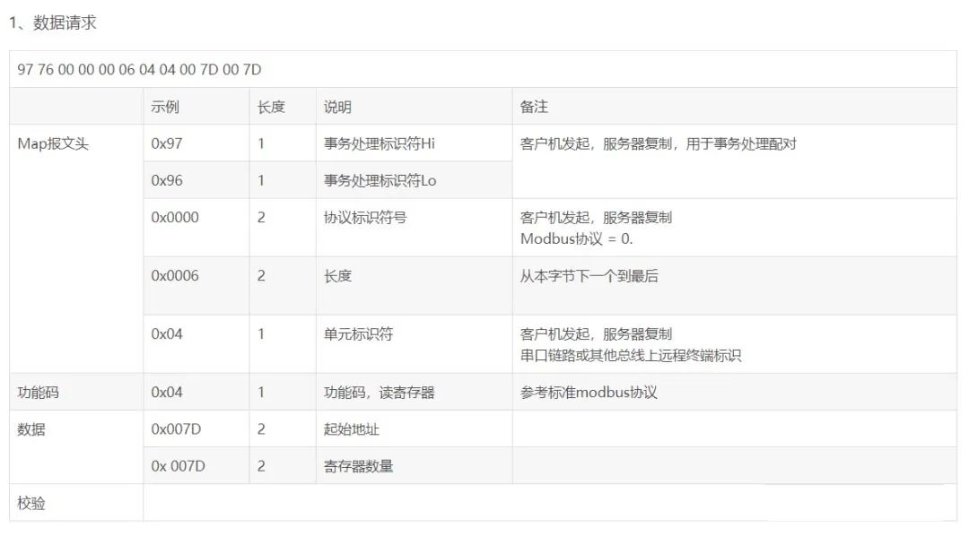
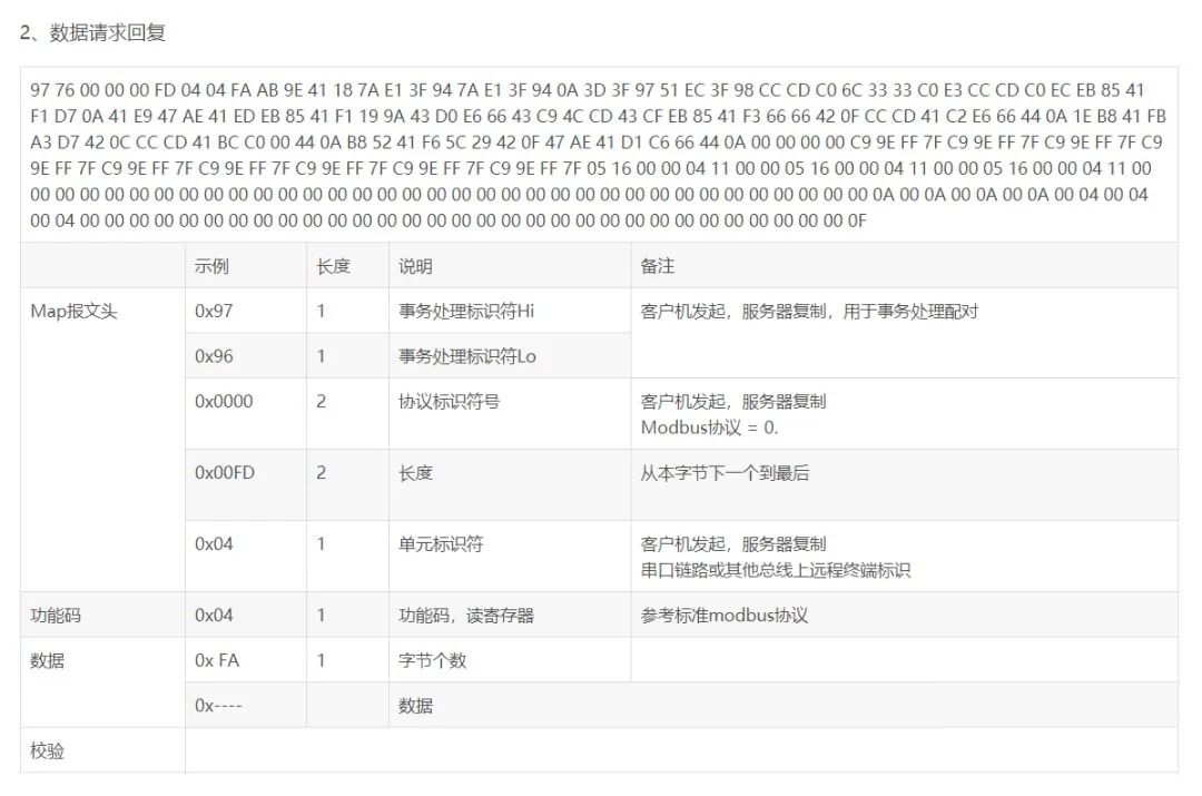
Modbus TCP Example Message
ModBusTcp and serial link Modbus have the same data field; specific data fields can refer to serial Modbus. Here are some ModbusTcp link analysis explanations to assist newcomers in analyzing messages.
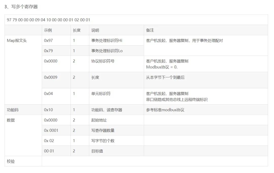
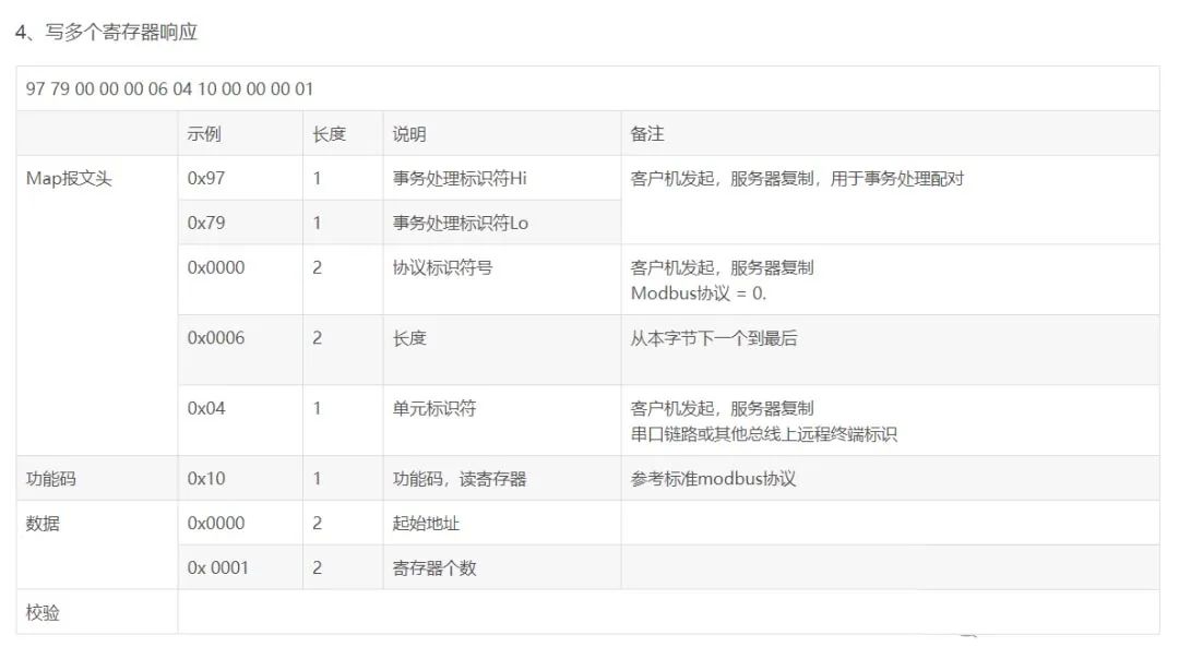
Function Code 0x10: Write Multiple Holding Registers, the above two images are incorrect.
Modbus TCP Communication
Communication Method
Modbus devices can be divided into master (poll) and slave. There is only one master, while there are multiple slaves. The master sends request frames to each slave, and the slave responds. When using TCP communication, the master is the client, actively establishing the connection; the slave is the server, waiting for the connection.
-
Master request: Function Code + Data
-
Slave normal response: Request Function Code + Response Data
-
Slave abnormal response: Abnormal Function Code + Exception Code, where the abnormal function code is the highest bit of the requested function code set to 1, and the exception code indicates the error type.
-
Note: A timeout management mechanism is needed to avoid indefinite waiting for a possible non-existent response.
IANA (Internet Assigned Numbers Authority) assigns TCP port number 502 to the Modbus protocol, which is currently the only port number allocated in the instrumentation and automation industry.
Communication Process
-
connect Establish TCP connection
-
Prepare Modbus message
-
Use send command to send the message
-
Wait for response on the same connection
-
Use recv command to read the message, completing one data exchange
-
At the end of the communication task, close the TCP connection
Simulation Software
-
Modbus Poll and Modbus Slave are a set of Modbus simulation software that can implement Modbus RTU, TCP, serial port simulation, etc.
-
Simulation software website: https://modbustools.com/download.html
-
In ModbusTCP, Modbus Poll acts as the client to request data, while Modbus Slave acts as the server to handle requests.
-
When writing a client to connect to Modbus Slave using C language, pay attention to the data format; a command must be sent all at once; otherwise, the connection will fail.
-
When using the software, it is necessary to specify the function code in the setup->slave definition or poll definition. – Slave ID: Slave number (transaction identifier) – Function: Function code, 0x01 corresponds to coil operation, 0x02 corresponds to discrete operation, 0x03 corresponds to holding register operation, 0x04 corresponds to input register operation – Address: Start address – Quantity: Number of registers/coils/discrete items
Some Concepts
In industrial automation control, various concepts such as switching quantity, digital quantity, analog quantity, discrete quantity, and pulse quantity are often encountered, and people can easily confuse these concepts in practical applications. Below are various concepts listed:
1. Switching Quantity
Generally refers to the “on” and “off” states of contacts, which are usually represented as “0” or “1” in computer devices.
Switching quantity can be divided into active switching quantity signals and passive switching quantity signals. Active switching quantity signals refer to signals whose “on” and “off” states are powered signals, professionally called step signals, which can be understood as pulse quantities;
Typically includes 220VAC, 110VAC, 24VDC, 12VDC signals; passive switching quantity signals refer to signals whose “on” and “off” states are not powered signals, commonly referred to as dry contacts. The resistance testing method is resistance 0 or infinity.
2. Digital Quantity
Many people confuse digital quantity with switching quantity and also with analog quantity. Digital quantity is a discrete physical quantity in both time and quantity, and the signal it represents is a digital signal. Digital quantity consists of signals made up of 0 and 1, encoded to form regular signals. The quantized analog quantity becomes digital quantity.
3. Analog Quantity
The concept of analog quantity corresponds to digital quantity but can be transformed into digital quantity after quantization. Analog quantity is a continuous physical quantity in both time and quantity, and the signal it represents is an analog signal. Any value taken during the continuous change of analog quantity is a specific meaningful physical quantity, such as temperature, voltage, current, etc.
4. Discrete Quantity
Discrete quantity is the physical quantity obtained by discretizing analog quantity. That is, any instrument or device cannot have a completely accurate representation of the analog quantity since they all have a sampling period, during which the physical quantity’s value remains unchanged, while the actual analog quantity is changing. This discretizes the analog quantity into a discrete quantity.
5. Pulse Quantity
Pulse quantity refers to the signal that instantaneously changes voltage or current from one value to another. After quantization, if its change continues regularly, it is digital quantity; if it changes from 0 to a fixed value and remains unchanged, it is switching quantity.
In summary, analog quantity is a physical quantity that continuously changes in time and quantity during a certain process. In practical applications, all instruments and devices for collecting external data have a sampling period, and the collected data only changes at the beginning of the next sampling period; during the sampling period, its value does not change with the change of analog quantity.
Thus, the analog signal is discretized. For example, if a device’s sampling period is 1 second, and the temperature collected at the fifth second is 35 degrees, while the temperature at the sixth second is 36 degrees, the device can only indicate the temperature at the fifth second as 35 degrees and at the sixth second as 36 degrees, while at the fifth and a half seconds, it can only indicate 35 degrees, but the actual analog quantity is 35.5 degrees. This discretizes the analog signal. The collected data is thus discretized and no longer a continuous analog signal.
Since computers only recognize two signals, 0 and 1, that is, switching quantity signals, numerical values are represented by digital strings. Due to computational limitations, these digital strings cannot be infinitely long, meaning their expressed precision is also limited. Taking temperature as an example, due to the limitations of digital strings, the precision of expressed temperature can only reach 0.1 degrees; values smaller than this unit cannot be indicated. Thus, discrete quantities must be quantified into digital quantities. For instance, a temperature of 35.68 degrees would be expressed as 35.6 degrees.
Recommended For You

“Zero-Based Introduction to Siemens 200SMART” is published by Hefei University of Technology,original price 128 yuan, fan exclusive benefit only 15 yuan, free shipping to home, limited to the first 50 people!

▲Details displayed, click to enlarge
15 yuan includes: 275-page full-color book + 22 video courses + programming software + simulation software + 100GB learning materials
Limited benefits, what are you waiting for? Hurry up and buy!👇

Disclaimer:This article is reproduced from the internet, and the copyright belongs to the original author. If there are copyright issues, please contact us in a timely manner for deletion, thank you!
2022 Electrician Level 1 Exam Question Bank Complete Version (Includes Answers)
Three must-have tools for electrical workers, easily opened with WeChat!
【Collect】 The “way out” for ten-year-old electricians, the secret to earning over ten thousand a month!
The five major electrical drawing software (CAD, Eplan, CADe_simu…), which one do you pick?
Latest electrical CAD drawing software, with super detailed installation tutorial!
Latest electrical drawing software EPLAN, with super detailed installation tutorial!
Common issues when beginners use S7-200 SMART programming software (with download link)
Super comprehensive electrical calculation EXCEL spreadsheet, generates automatically! No need to ask for electrical calculations!
Bluetooth headsets, electrical/PLC introductory books are given away? Come and claim your electrical gift!
Basic skills of PLC programming: Ladder diagrams and control circuits (with 1164 practical cases of Mitsubishi PLC)
Still can’t understand electrical diagrams? Basics of electrician’s diagram recognition, simulation software to take away, theory and practice quickly get started!
12 free electrician video tutorials, 10GB software/eBook materials, and 30 days of free electrician live courses are being given away!