The Modbus RTU communication protocol uses a master-slave response method for data communication. Requests can only be initiated by the master (PC, HMI, etc.) through a unique slave address, and the slave (terminal device) responds to the master’s requests, thus enabling half-duplex communication. This protocol only allows the master to initiate requests, and the slave responds passively, so the slave does not actively occupy the communication line, preventing data conflicts.
Similar master-slave response protocols to Modbus RTU include Siemens PPI and DL/T645-2007 commonly used in electric meters.
1. Protocol Format
Information transmission is asynchronous and uses hexadecimal for communication. The information frame format is as follows:
|
Address Code |
Function Code |
Data Area |
CRC Check Code |
|
1 byte |
1 byte |
N bytes |
2 bytes |
Address Code
The address code is the first byte of each communication information frame, generally supporting 1 to 247. Some devices also support address 0 for receiving broadcast data from the master. Each slave must have a unique address on the bus, and only the slaves with address codes matching the master can respond with data.
Function Code
The function code is the second byte of each communication information frame. The master sends it to inform the slave device what operation it should perform.
The eight common function codes are:
|
Function Code |
Definition |
Operation |
|
01H |
Read Coil |
Read the status of one or more continuous coils |
|
05H |
Write Single Coil |
Operate the state of a specified coil |
|
0FH |
Write Multiple Coils |
Operate multiple continuous coil statuses |
|
02H |
Read Discrete Input |
Read the status of one or more continuous discrete inputs |
|
04H |
Read Input Register |
Read data from one or more continuous input registers |
|
03H |
Read Holding Register |
Read data from one or more holding registers |
|
06H |
Write Single Holding Register |
Write two hexadecimal data to the corresponding position |
|
10H |
Write Multiple Holding Registers |
Write 4*N hexadecimal data to N continuous holding registers |
Data Area
The data area varies depending on the function code and data direction. This data can be combinations such as “register starting address + number of registers to read”, “register address + operation data”, “register starting address + number of registers to operate + data length + data”, and the details of different function codes are explained in the “Function Code Analysis” section.
Modbus CRC Check
The Modbus RTU protocol is commonly used in industrial sites where data transmission stability and accuracy are required, thus ensuring data transmission correctness and integrity through CRC checks.
2. Error Feedback
Errors in address and CRC checks will not receive data feedback from the slave, while other errors will return error codes to the master. The second byte of the data frame plus 0X80 indicates that a request error has occurred (illegal function code, illegal data value, etc.), and the error data frame is as follows:
|
Address Code |
Function Code |
Error Code |
CRC Check Code |
|
1 byte |
1 byte |
1 byte |
2 bytes |
The common error codes are as follows:
|
Value |
Name |
Description |
|
01H |
Illegal Function Code |
The function code operation register is not supported |
|
02H |
Illegal Register Address |
Accessing a register that is prohibited for the device |
|
03H |
Illegal Data Value |
Writing unsupported parameter values |
|
04H |
Slave Device Failure |
The device is operating abnormally |
3. Communication Information Transmission Process
When the communication command is sent from the master to the slave, the slave with the address code matching that of the master receives the command. If the CRC check is correct, it executes the corresponding operation and returns the execution result (data) to the master. The returned information includes the address code, function code, executed data, and CRC check code. If the address does not match or the CRC check fails, no information is returned.
4. Function Code Analysis
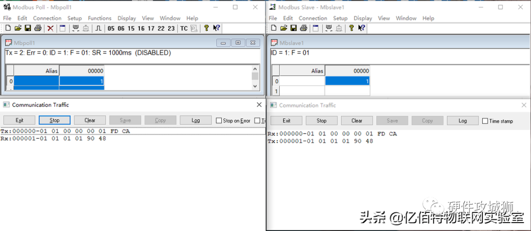
Function Code 01H: Read Coil
For example, if the master wants to read the status of one coil at starting address 00H from slave address 01H, the master sends:
|
Master Sends |
Sent Data (HEX) |
|
|
Address Code |
01 |
|
|
Function Code |
01 |
|
|
Starting Coil Address |
High Byte |
00 |
|
Low Byte |
00 |
|
|
Coil Quantity |
High Byte |
00 |
|
Low Byte |
01 |
|
|
CRC Check |
Low Byte |
FD |
|
High Byte |
CA |
If the coil at register 00H is closed, the slave returns:
|
Slave Returns |
Sent Data (HEX) |
|
|
Address Code |
01 |
|
|
Function Code |
01 |
|
|
Byte Count |
01 |
|
|
Coil Status |
01 |
|
|
CRC Check Code |
Low Byte |
90 |
|
High Byte |
48 |
Simulation demonstration:
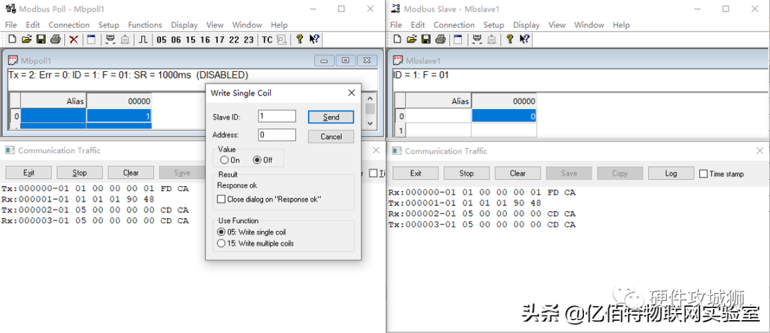
Function Code 05H: Write Single Coil
For example, if the master wants to control the coil status at address 0000H of slave address 01H, the master sends:
|
Master Sends |
Sent Data (HEX) |
|
|
Address Code |
01 |
|
|
Function Code |
01 |
|
|
Coil Address |
High Byte |
00 |
|
Low Byte |
00 |
|
|
Control Mode |
High Byte |
00 (Off), FF (On) |
|
Low Byte |
01 |
|
|
CRC Check |
Low Byte |
XX |
|
High Byte |
XX |
The slave returns the same as the master request;
Simulation demonstration:
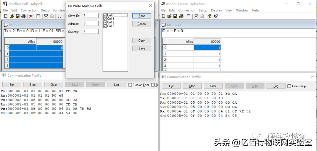
Function Code 0FH: Write Multiple Coils
For example, if the master wants to control the status of 4 coils starting from address 00H of slave address 01H, the master sends:
|
Master Sends |
Sent Data (HEX) |
|
|
Address Code |
01 |
|
|
Function Code |
0F |
|
|
Starting Coil Address |
High Byte |
00 |
|
Low Byte |
00 |
|
|
Coil Quantity |
High Byte |
00 |
|
Low Byte |
04 |
|
|
Bytes to Write |
01 |
|
|
Control Mode |
00 (All Off), 0F (All On) |
|
|
CRC Check |
Low Byte |
XX |
|
High Byte |
XX |
After operation of function code 0FH, the slave returns:
|
Slave Returns |
Sent Data (HEX) |
|
|
Address Code |
01 |
|
|
Function Code |
0F |
|
|
Starting Coil Address |
High Byte |
00 |
|
Low Byte |
00 |
|
|
Coil Quantity |
High Byte |
00 |
|
Low Byte |
04 |
|
|
CRC Check |
Low Byte |
54 |
|
High Byte |
08 |
Simulation demonstration:
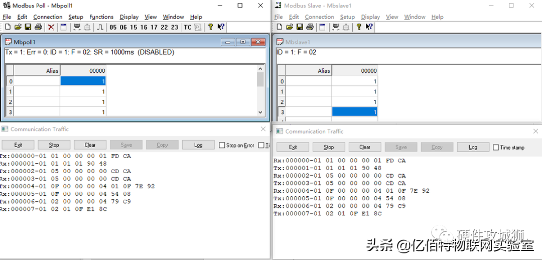
Function Code 02H: Read Discrete Input
For example, if the master wants to read the status of 4 discrete inputs starting from address 00H of slave address 01H, the master sends:
|
Master Sends |
Sent Data (HEX) |
|
|
Address Code |
01 |
|
|
Function Code |
02 |
|
|
Starting Discrete Input Address |
High Byte |
00 |
|
Low Byte |
00 |
|
|
Reading Quantity |
High Byte |
00 |
|
Low Byte |
04 |
|
|
CRC Check |
Low Byte |
79 |
|
High Byte |
C9 |
If the 4 discrete inputs starting from address 00H are all detected, the slave returns:
|
Slave Returns |
Sent Data (HEX) |
|
|
Address Code |
01 |
|
|
Function Code |
02 |
|
|
Byte Count |
01 |
|
|
Discrete Input Status |
0F |
|
|
CRC Check Code |
Low Byte |
E1 |
|
High Byte |
8C |
Simulation demonstration:
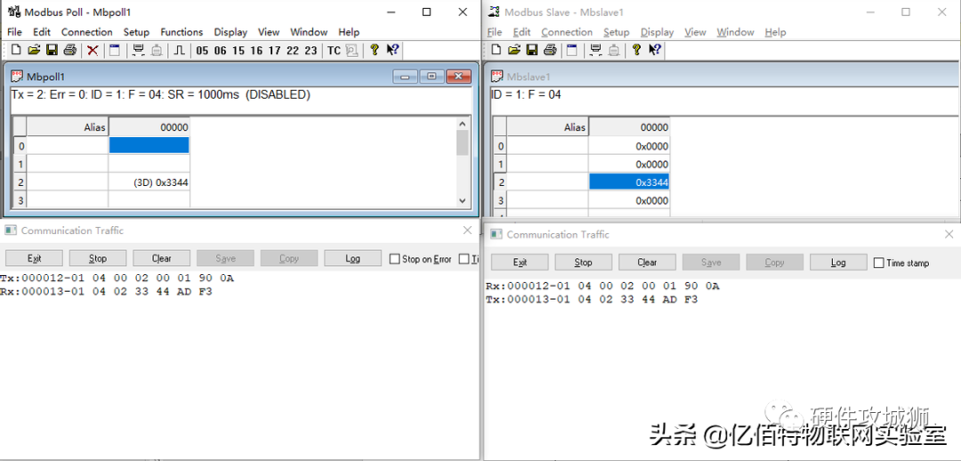
Function Code 04H: Read Input Register
For example, if the master wants to read data from one input register starting at address 02H of slave address 01H, the master sends:
|
Master Sends |
Sent Data (HEX) |
|
|
Address Code |
01 |
|
|
Function Code |
04 |
|
|
Starting Register Address |
High Byte |
00 |
|
Low Byte |
02 |
|
|
Register Quantity |
High Byte |
00 |
|
Low Byte |
01 |
|
|
CRC Check |
Low Byte |
90 |
|
High Byte |
0A |
If the input register at address 02H of the slave contains data 3344H, the slave returns:
|
Slave Returns |
Sent Data (HEX) |
|
|
Address Code |
01 |
|
|
Function Code |
04 |
|
|
Byte Count |
02 |
|
|
Register 05H Data |
High Byte |
33 |
|
Low Byte |
44 |
|
|
CRC Check Code |
Low Byte |
AD |
|
High Byte |
F3 |
Simulation demonstration:
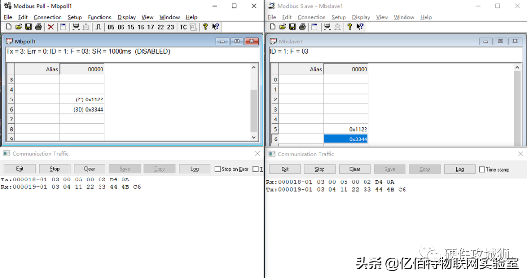
Function Code 03H: Read Holding Register
For example, if the master wants to read data from two holding registers starting at address 05H of slave address 01H, the master sends:
|
Master Sends |
Sent Data (HEX) |
|
|
Address Code |
01 |
|
|
Function Code |
03 |
|
|
Starting Register Address |
High Byte |
00 |
|
Low Byte |
05 |
|
|
Register Quantity |
High Byte |
00 |
|
Low Byte |
02 |
|
|
CRC Check |
Low Byte |
D4 |
|
High Byte |
0A |
If the holding registers 05H and 06H of the slave contain data 1122H and 3344H, the slave returns:
|
Slave Returns |
Sent Data (HEX) |
|
|
Address Code |
01 |
|
|
Function Code |
03 |
|
|
Byte Count |
04 |
|
|
Register 05H Data |
High Byte |
11 |
|
Low Byte |
22 |
|
|
Register 06H Data |
High Byte |
33 |
|
Low Byte |
44 |
|
|
CRC Check Code |
Low Byte |
4B |
|
High Byte |
C6 |
Simulation demonstration:
Function Code 06H: Write Single Holding Register
For example, if the master writes the data 9988H to the holding register at address 0050H of slave address 01H, the master sends:
|
Master Sends |
Sent Data (HEX) |
|
|
Address Code |
01 |
|
|
Function Code |
06 |
|
|
Register Address |
High Byte |
00 |
|
Low Byte |
50 |
|
|
Value to Write |
High Byte |
99 |
|
Low Byte |
88 |
|
|
CRC Check |
Low Byte |
E3 |
|
High Byte |
ED |
The slave returns the same as the master request;

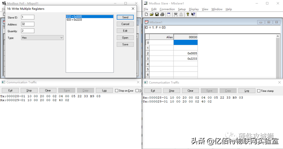
Function Code 10H: Write Multiple Holding Registers
For example, if the master wants to save the data 0005H and 2233H to two registers at slave address 01H, starting from register address 0020H, the master sends:
|
Master Sends |
Sent Data (HEX) |
|
|
Address Code |
01 |
|
|
Function Code |
10 |
|
|
Starting Register Address |
High Byte |
00 |
|
Low Byte |
20 |
|
|
Register Quantity |
High Byte |
00 |
|
Low Byte |
02 |
|
|
Bytes to Write |
04 |
|
|
0000H Register to Write |
High Byte |
00 |
|
Low Byte |
05 |
|
|
0001H Register to Write |
High Byte |
22 |
|
Low Byte |
33 |
|
|
CRC Check |
Low Byte |
B9 |
|
High Byte |
03 |
After operation of function code 10H, the slave returns:
|
Slave Returns |
Sent Data (HEX) |
|
|
Address Code |
01 |
|
|
Function Code |
10 |
|
|
Starting Register Address |
High Byte |
00 |
|
Low Byte |
20 |
|
|
Register Quantity |
High Byte |
00 |
|
Low Byte |
02 |
|
|
CRC Check |
Low Byte |
40 |
|
High Byte |
02 |
Simulation demonstration:
Source: https://www.toutiao.com/article/7116728597582299656
 Statement:This article is reprinted from “Toutiao – Yibai Technology IoT Laboratory”, copyright belongs to the author. If there is any infringement, please contact us for deletion!
👇 Click Follow, Technology Content Delivered on Time! 👇

-
What is the relationship between Fourier Transform, Laplace Transform, and Z Transform? Why perform these transforms?
-
Those once popular microcontrollers~
-
Can you imagine a Bluetooth chip costing less than 2 yuan?
-
Why do domestic chips also use English to write “datasheet”?
-
Wonderful operational amplifier circuits
-
Why is it 50 ohms???
-
The most detailed basics of diodes
-
What is a BSP engineer?