The Modbus protocol is arguably the most widely used communication protocol in the field of industrial automation. Its openness, scalability, and standardization make it a universal industrial standard. With it, products from different manufacturers can be easily and reliably connected to the network, achieving centralized monitoring and decentralized control functions.
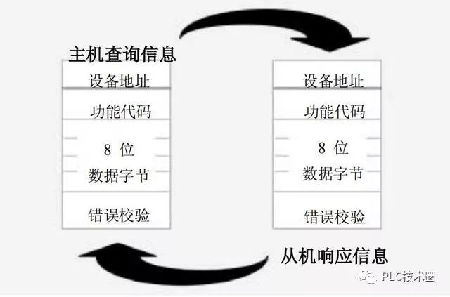
Currently, the Modbus specifications mainly use ASCII, RTU, TCP, etc., and do not specify the physical layer. The commonly used interface forms for Modbus include RS-232C, RS485, RS422, and those using RJ45 interfaces. The Modbus ASCII and RTU protocols specify the structure of messages, data, commands, and responses based on these interfaces. Modbus data communication adopts a Master/Slave method, where the Master sends data request messages, and upon receiving the correct message, the Slave can send data back to the Master in response to the request; the Master can also directly send messages to modify the Slave’s data, enabling bidirectional read/write.
In serial communication, the “baud rate” is used to describe the rate of data transmission. An international standard baud rate series includes: 110, 300, 600, 1200, 1800, 2400, 4800, 9600, 14.4Kbps, 19.2Kbps, 28.8Kbps, 33.6Kbps, 56Kbps. For example, 9600bps indicates that 9600 bits are transmitted per second, including the number of characters and other necessary bits such as start bits, stop bits, and parity bits.
In the field of automation, we often use the RTU mode. In the RTU mode, the format of each byte is as follows:
Encoding system: 8-bit binary, hexadecimal 0-9, A-F
Data bits: 1 start bit
8 data bits, low bit first
1 bit for odd/even parity; 0 bits if no parity
1 stop bit with parity; 2 stop bits without parity
Error check area: Cyclic Redundancy Check (CRC)
Slave address setting: The information address consists of 2 characters (ASCII) or 8 bits (RTU), with a valid slave device address range of 0-247 (decimal).
Function code setting: The information frame function code consists of characters (ASCII) or 8 bits (RTU). Valid code range is 1-225 (decimal);
Content of the data area: The data area contains 2 hexadecimal data bits, with a data range of 00-FF (hexadecimal). Depending on the method of serial transmission over the network, the data area can consist of a pair of ASCII characters or a single RTU character.
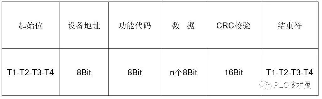
Message frame of the RTU mode:
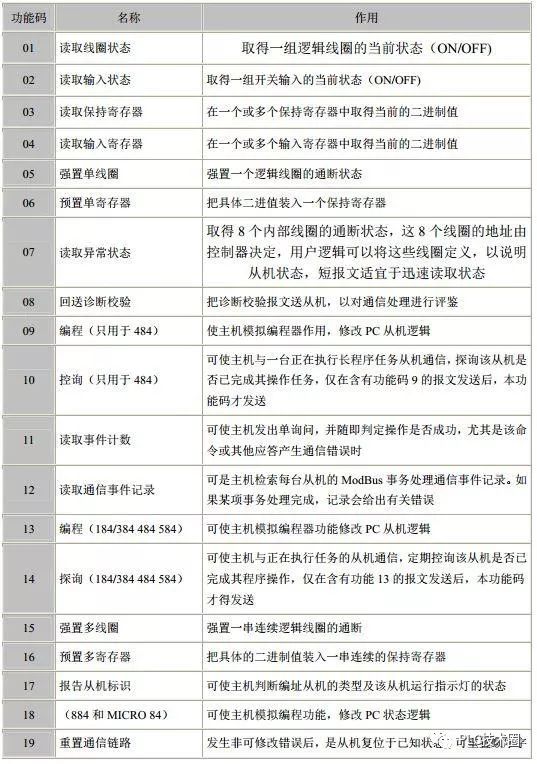
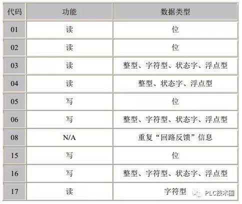
Function codes of Modbus:
Modbus function code and data type correspondence table:
Example of reading whole data in RTU mode:
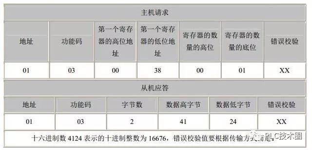
Let’s analyze: The host sends a command to access the slave address 1, using function code 03 (read holding registers), with the starting address high 8 bits and low 8 bits: indicating the starting address of the analog quantity to be read (starting address is 0). For example, the starting address in this example is 38, which is 56 in decimal. The number of registers high 8 bits and low 8 bits: indicates how many analog quantities to read from the starting address. In this example, it is 1 analog quantity. Note that in the returned information, one analog quantity requires two bytes to be returned. The error check is CRC check.
Slave response: The device address and command number are the same as above. The returned byte count indicates the number of data bytes, which is the value of n in data 1, 2…n. In this example, 1 analog quantity data is returned, and since one analog quantity requires 2 bytes, a total of 2 bytes are returned. The high and low bytes of the data: 41 and 24 represent the value of the returned analog quantity, which is 16676 in decimal. The error check is CRC check.
Qicheng Intelligent
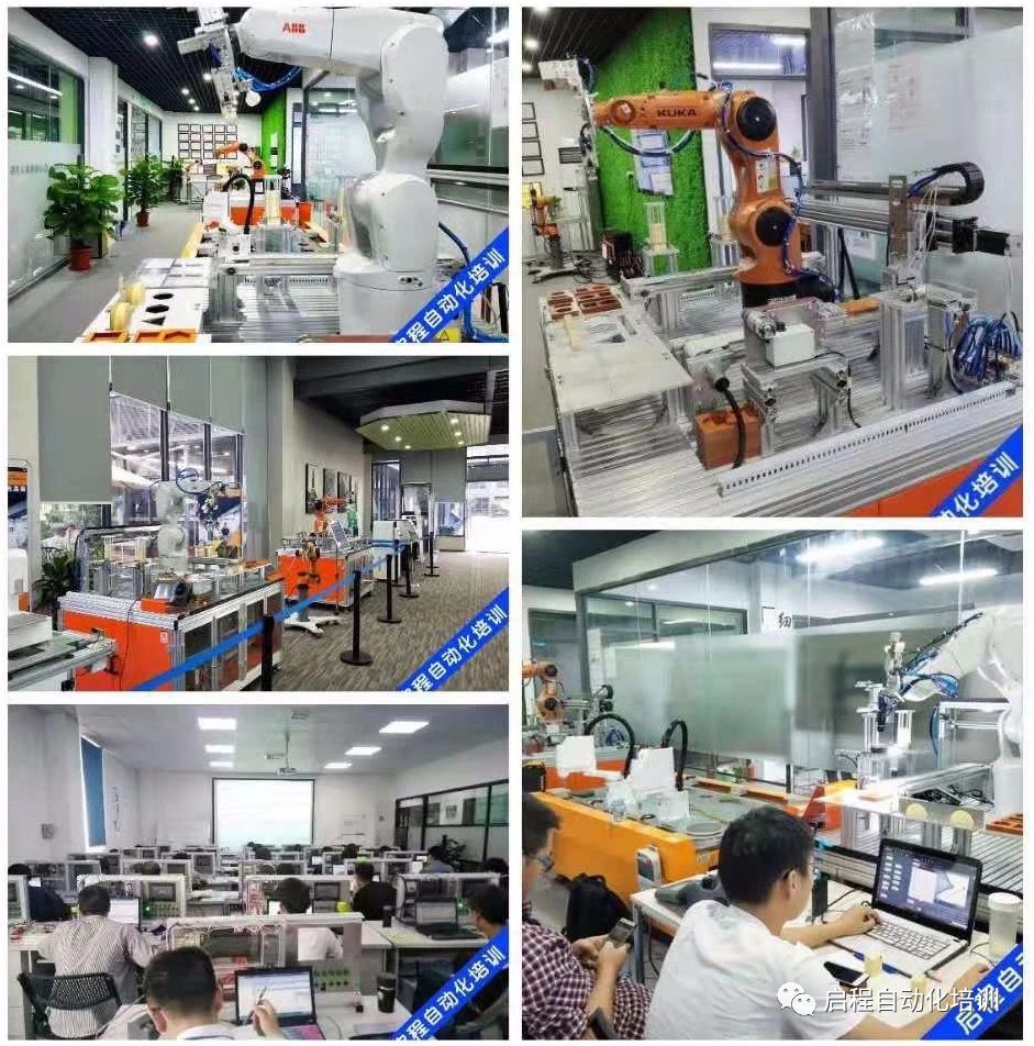
About Us: Qicheng Automation Training is China’s leading industrial robot training service provider.
Contact Number: 13809869603
Training Programs: Robotics, PLC system integration, machine vision
Special Services: 3000 square meters training center + recommended employment + industry-leading curriculum system
Address: Shajing 107 Huiju Chuangzhi Park, Baoan District, Shenzhen

+ Teacher WeChat, inquire about course details