Limited Time Download | Complete Learning Materials for ABB and FANUC Robots
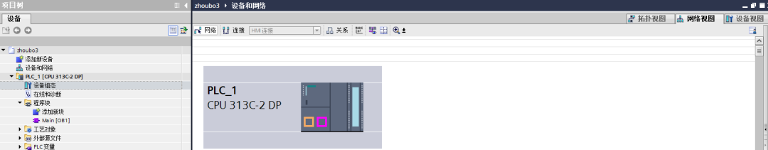
In TIA Portal, create a new project. This case selects Siemens S7-300 PLC, model CPU 313C-2DP. This PLC is an integrated PLC with a built-in PROFIBUS-DP port, which can act as either a master or a slave. In this case, the PLC acts as the master.
Step 1: Add the GSD file.
In TIA Portal, click on “Options” and then “Manage General Station Description Files” as shown in the figure below:
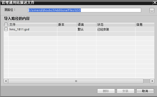
Select the GSD file and click install. The installation time may vary depending on the computer.
Step 2: Double-click “Device Configuration” and switch the view to network view, as shown in the figure below:
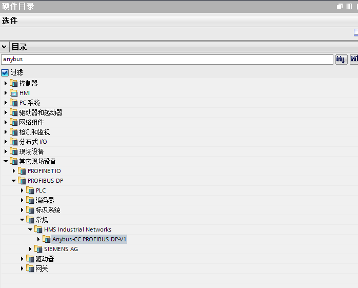
Step 3: In the search bar of the “Hardware Catalog” function area on the right, enter “anybus”, and the following search results will appear:
Step 4: Expand Anybus-CC PROFIBUS DP-V1 and click and drag it into the network view, as shown in the figure below:
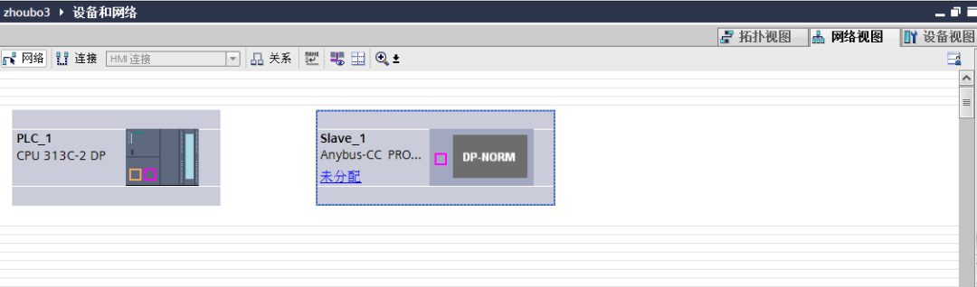
Step 5: Hold down the left mouse button to select the DP port of PLC_1 and connect it to the DP port of slave_1, as shown in the figure below:
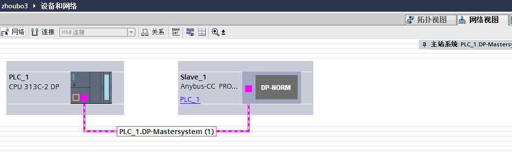
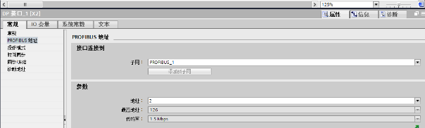
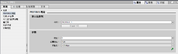
At this point, the hardware configuration between the PLC and the robot is complete. To ensure accuracy, we need to check the addresses of the master and slave. By default, the PLC, as the master, has an address of 2, while Slave_1, the robot end, has a default address of 3, as shown below:
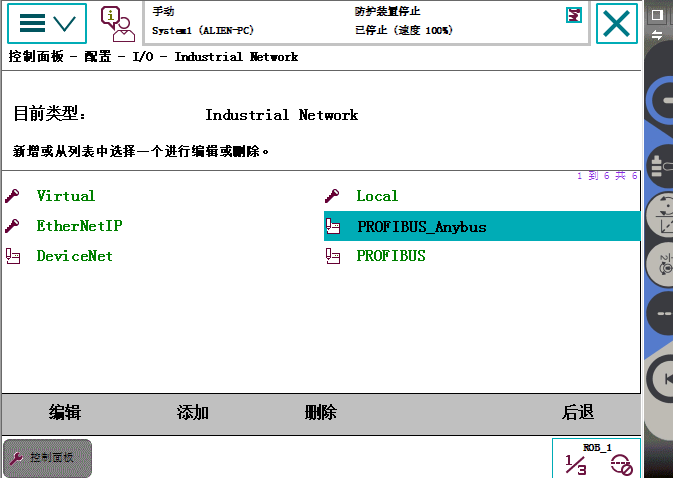
Step 1: In the “Configuration” menu of the teach pendant, ensure that the system supports Industrial Network, expand Industrial Network and ensure that PROFIBUS_Anybus exists in the system, as shown in the figure below:
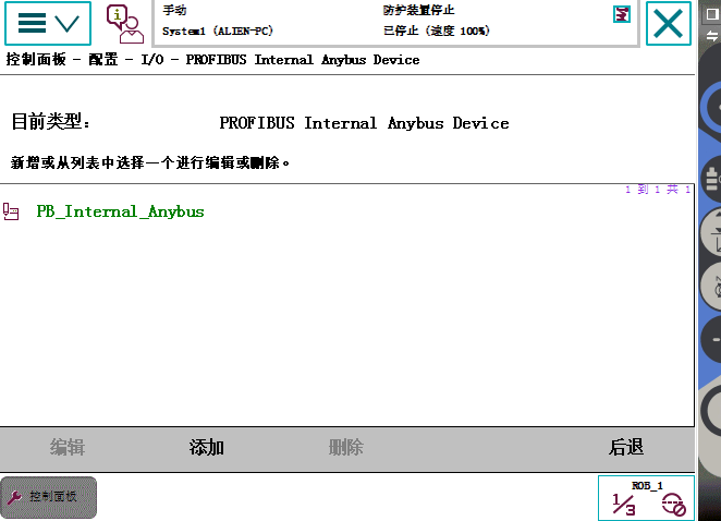
Step 2: In the “Configuration” menu, expand PROFIBUS Internal Anybus Device, as shown in the figure below:
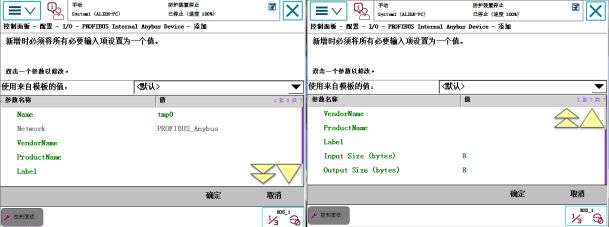
Step 3: If PB_Internal_Anybus appears in step two, no addition is needed, if it does not appear, add it as shown in the figure below:
In the Name field, enter a name, and fill in Input Size (bytes) and Output Size (bytes) with the corresponding communication capacity, which supports a maximum of 512 bits or 64 bytes. No other content needs to be changed. After adding, click OK.
The communication program on the PLC side is relatively simple; it only requires moving the corresponding bit values to the appropriate addresses. In this case, the PLC and robot communicate using one byte of input and output.
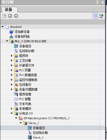
Step 1: Expand the Distributed I/O under the project tree on the left, expand it in turn, find Device Configuration, and double-click. As shown in the figure below:
Step 2: In the Hardware Catalog menu on the right, find “Input 1 byte” and “Output 1 byte”, and double-click them respectively, to make them appear under Slave_1 on the left. This step tells the PLC that each time it sends and receives data with the robot, it is done in one byte units. As shown in the figure below:
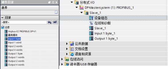
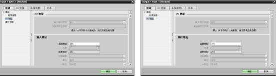
Step 3: Determine the communication addresses of the PLC. This step is crucial as it relates to how addresses are determined within the program, select “Input 1 byte” and “Output 1 byte” respectively, right-click, and select “Properties”. The default addresses can be used here, as shown below:
At this point, all configurations have been set up.
Final Step: Add the following program in the Main program block:
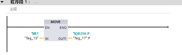
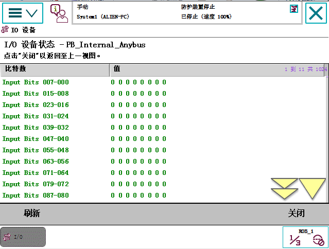
This program indicates that the PLC sends the status value of the first byte from channels 1.0-1.7 to 256.0-256.7, where 256.0-256.7 corresponds to the first byte of the robot’s receiving end. We can monitor this in the IO monitoring interface of the robot teach pendant as shown below:
——-End——-
Source: Original by Teacher Zhou from the Guidance Car. For reprinting, please leave a message in the background.
How to Enter the Industrial Robot Industry?
|
March 5th |
Industrial Robot Application Engineer Training Class Mechanical Design, Electrical Design,Debugging and Maintenance Teacher Tu 18042310501
|
Hangzhou |
|
March 12th |
Industrial Robot Application Engineer Training Class Debugging and Maintenance Teacher Lu 15899838594
|
Guangdong |
|
March 19th |
Industrial Robot Application Engineer Training Class Debugging and Maintenance Teacher You 18623394750
|
Chongqing |


Follow the public account, reply AF, to obtain ABB and FANUC materials

Only a Follow Away from Becoming an Industrial Robot Expert
Guidance Car Robot Academy, Cradle of Robot Engineers
< Previous Classic Articles >
-
Japanese Say Kneel, Few Robots Can Stand Globally | The Beauty of Precision Reducers Transmission
-
Become an Electrical Diagram Expert in 3 Minutes
-
Industrial Robot Maintenance, Characteristics, Advantages, Structural Composition, Technical Principles, and Types
-
Read This Article to Master 15 Basic Concepts of PID【Super Content】Collection of Knowledge Related to Robot Control Systems
-
Open Up KUKA Robots and Explore Their Secrets
-
The Most Comprehensive ABB Robot Technical Training Materials, After Reading You Will Also Be an ABB Robot Expert!
-
Introduction to Mitsubishi PLC Programming Software
-
How to Operate Major Brands of Industrial Robots – Cognitive Edition
-
Video | FANUC Robot Walking Axis Motion Simulation Tutorial, Including Download Address and Operation Manual
-
How Much Do You Know About the Important Applications of Industrial Robots? | Analysis
-
The Ten Thousand Whys of Motors 【Turned】
-
Mechanical Animation | Summary of Working Principles and Videos of Various Models of Compressors
-
The Design Process of Industrial Robots is Not Simple!
-
CAD Drawing Mnemonics, Everyone Gets One, Pass It On and Memorize It!
-
Industrial Robot Maintenance, Characteristics, Advantages, Structural Composition, Technical Principles, and Types
-
First Time Seeing Someone Use Images to Explain Major Assembly Lines of Cars So Clearly, It’s Too Comprehensive
-
56 PPTs to Help You Understand Servo Motor Control Technology
-
ABB Robot Teach Pendant Introduction – Beginner’s Teaching | Content
-
Industrial Robot Virtual Simulation Delmia: Industrial Robot Walking Axis Simulation | Content