1
Installation Specifications for Communication and Positioning Service Modules
The communication and positioning service module is a standard module in the base station’s intelligent environmental monitoring unit (FSU), which monitors the geographical location, status, and environment of the tower.
1.1 Technical Specifications
● Operating Environment: Control Module: Temperature -10℃ to +50℃, Humidity: ≤95%RH; Front-end Equipment: -40℃ to +85℃.
● Operating Voltage: Control Module: +12VDC; Front-end Equipment: -48VDC. The control module requires electrical isolation for all ports (power, serial) of the front-end equipment, with an isolation strength requirement of DC 5KV.
● Operating Current: Control Module: No more than 100mA@12V; Front-end Module Operating Current: No more than 200mA@48V.
1.2 FSU Interface
The data line connects to one of the USB ports of the FSU, and the control line connects to the DO interface of the FSU. The specific wiring method is implemented according to the definitions of each FSU manufacturer. Power supply is implemented according to the definitions of different module models.
1.3 Installation Specifications
● The installation location should be reasonable, securely fixed without looseness; when the main unit is installed in a cabinet, the module should be installed on the side of the main unit, secured with cable ties, without occupying cabinet space.
● Wireless and GPS antennas should be placed outdoors, with the specific location installed according to signal strength. The installation should be secure, and the antennas should be placed as discreetly as possible to avoid direct sunlight.
● Wireless and GPS antennas should be installed within the 45° protection angle of the lightning rod, and the brackets and mounting rods must be well grounded.
● The GPS antenna should be installed in a relatively open area, with no buildings obstructing the 90-degree range above (at least 45° to the south), and the antenna should be installed vertically.
2
Installation Specifications for Temperature and Humidity Sensors
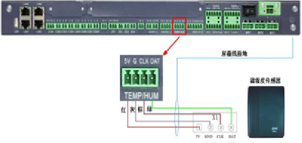
The temperature and humidity sensor can directly convert the two basic physical signals of temperature and humidity into electrical signals and transmit the detection data to the FSU to achieve monitoring of the on-site temperature and humidity.
2.1 Technical Specifications
● Temperature Measurement Range: -20℃ to 80℃
● Humidity Measurement Range: 0—100%RH
● Temperature Measurement Accuracy: ≤±1℃
● Humidity Measurement Accuracy: ≤±5%RH (at an ambient temperature of 25℃, humidity range of 30%RH to 80%RH)
● ≤10%RH (at an ambient temperature of 25℃, humidity range <30%RH or >80%RH)
2.2 FSU Interface
Connect to the AI interface of the FSU, with the specific wiring method implemented according to the definitions of each FSU manufacturer.
2.3 Installation Specifications
● Should be installed in a location that can stably reflect the temperature/humidity of the machine room, and should not be installed in the following locations: near doors, air conditioning intake and exhaust ports, near windows, near water vapor and volatile oil vapors, and near equipment heat dissipation ports.
● Indoor stations should be installed on the wall with self-tapping screws or adhesive plugs, securely fixed, and should use specialized high-temperature adhesives, such as epoxy resin. Outdoor stations should be secured with cable ties according to the situation inside the cabinet.
● The installation height should facilitate maintenance, with the bottom of the sensor 150cm from the ground (±10cm depending on actual conditions). The sensor should use a raised base to minimize the temperature radiation from the wall to the sensor probe.
● When using a single bus connection, the number of sensors should not exceed 4; when using RS485 connection, it should not exceed 8.
3
Installation Specifications for Smoke Sensors
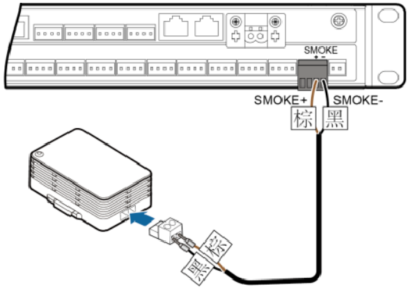
The smoke detector is a device that prevents fire by monitoring the concentration of smoke, transmitting detection data to the FSU for real-time monitoring.
3.1 Technical Specifications
● Operating Voltage: DC12V±10% or DC24V±10%.
● Static Current: ≤100μA.
● Alarm Current: ≤30mA.
● Output Form: Photoelectric alarm.
● Protection Area: 60m² (installation height less than 6m).
● Operating Temperature: -10℃ to +50℃.
● Operating Relative Humidity: ≤95% (at 40℃±2℃).
3.2 FSU Interface
Connect to the DI interface of the FSU, with the specific wiring method implemented according to the definitions of each FSU manufacturer.
3.3 Installation Specifications
● Should be installed on the ceiling above the switch power supply. Should not be installed in the following locations: on beams and wire racks; in places with significant dust, water mist, oil mist pollution, or corrosive gases; near air conditioning outlets and intakes.
● Use self-tapping screws or adhesive plugs for installation, and specialized high-temperature adhesives, such as epoxy resin, should be used to ensure secure and stable installation.
● The horizontal distance from the detector to the air conditioning outlet should be greater than 1.5 meters, and the horizontal distance from walls and beams should not be less than 0.5 meters.
● Smoke sensors can be installed in parallel, but the number of parallel installations should not exceed 5. Detectors in different rooms should not share a DI port in parallel.
● During the installation of the smoke detector, the plastic cover of the front probe must not be opened to prevent dust contamination during construction, which could affect sensitivity.
4
Installation Specifications for Water Leakage Sensors
The water leakage sensor detects the presence of water through electrodes to promptly inform about water ingress in the on-site machine room.
4.1 Technical Specifications
● Operating Power Supply: DC12V±10% or DC24V±10%;
● Power Consumption: ≤30mA;
● The input, output, and power supply of the detector must be isolated from each other, with an isolation withstand voltage of not less than 1000V/min·1mA;
● Detection Sensitivity: 40KΩ±10KΩ;
4.2 FSU Interface
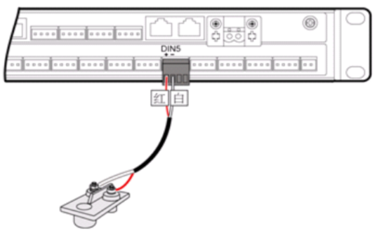
Connect to the DI port of the FSU, with the specific wiring method implemented according to the definitions of each FSU manufacturer.
4.3 Installation Specifications
● Indoor stations should be installed next to the air conditioning unit or at the lowest horizontal point in the machine room; outdoor stations should be installed at the lowest horizontal point in the cabinet. For machine rooms built in low-lying areas, a water leakage sensor can be added at the entrance of the machine room. Ensure that the sensor probe is in close contact with the ground during installation.
● Should be kept away from strong electrical sources and heat sources, and should not be close to chemical reagents, oils, etc.
5
Installation Specifications for Infrared Detectors
The infrared detector is a device that generates alarms using infrared rays, capable of sensing moving objects within the machine room to promptly detect unauthorized entry.
5.1 Technical Specifications
● Detector Angle: 90 degrees;
● Detection Range: 12m x 12m;
● Detection Distance: Adjustable/from 25% to 100% (3m to 12m);
● Operating Temperature: -5℃ to +55℃, with a 60-second preheat;
● Power Consumption: Operating current <20mA; alarm current <36mA, power supply 12VDC;
● Alarm Relay: NC type (both solid-state and coil types are acceptable), can withstand 0.1A/24VDC, contact resistance <18 ohms;
● Tamper Switch: NC type, 50mA/30VDC;
● Installation Height: 2.15m to 4.50m;
● Operating Voltage: 12VDC±10% or DC24V±10%.
5.2 FSU Interface
Connect to the DI interface of the FSU, with the specific wiring method implemented according to the definitions of each FSU manufacturer.
5.3 Installation Specifications
● Should be installed on the wall facing doors and windows, and should not be installed near heating or cooling equipment.
● Use self-tapping screws or adhesive plugs for installation, and all screws for securing the device’s mounting ears should be fully installed.
● The installation height of the detector should be 2.1m to 2.3m from the ground (or floor).
● Do not place large objects in front of the detector, and do not orient the detector towards outdoor passages or rotating machinery.
6
Installation Specifications for DC Voltage Transmitters
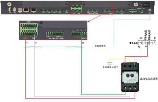
The DC voltage transmitter is a device that isolates and transmits DC voltage into a linear DC analog signal. Its main function is to detect the battery voltage within the base station.
6.1 Technical Specifications
● Accuracy: ±0.5%;
● Input (DC): 0V to 60V;
● Output: Current type DC 4mA to 20mA, Voltage type DC0V to DC5V;
● Auxiliary Power Supply: DC12V±10% or DC24V±10%;
● Input Terminal Lightning Protection Index: Input line against ground 3000A nominal discharge current, using 8/20us current waveform, 5 times for both positive and negative levels;
● Output terminal and auxiliary power supply terminal withstand surge voltage: 2000V, using 1.2/50us voltage waveform, 5 times for both positive and negative levels.
6.2 FSU Interface
Connect to the AI interface of the FSU, with the specific wiring method implemented according to the definitions of each FSU manufacturer.
6.3 Installation Specifications
● The sampling position should be on the positive and negative terminals of the battery group or the main cable, with a fuse soldered in between, and the sampling wire should be fixed to the busbar or terminal post.
● Sampling on the positive and negative busbars of the switch power supply is strictly prohibited.
● Each battery group should install one set of transmitters. Indoor stations should fix the transmitter on the wall near the battery, ensuring all screws for securing the device’s mounting ears are fully installed. Outdoor stations should be secured with cable ties according to the situation inside the cabinet.
7
Installation Specifications for Cameras
7.1 Technical Specifications
● Operating Environment: -10℃ to 50℃
● Power Supply: DC12V ±10%
● Power Consumption: <3W
● Minimum Illumination: 0.01Lux
● Lens Aperture: Fixed aperture
● Lens Focal Length: 3.6mm
● Network Interface: 1 RJ45 10M/100M adaptive Ethernet port
● Micro SD Card Storage: Supports 32GB
● Video Compression Standard: H.264 / MJPEG
● Video Character Overlay: Can set to display video channel name, time, date
● Image Settings: Supports mirroring and flipping
● Audio Compression Format: G.711A/G.711U/G.726
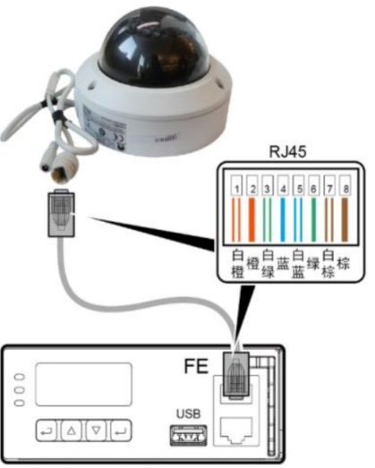
7.2 FSU Connection Method
Connect to the network port of the FSU, with power supply connected to the 12V port of the FSU. The specific wiring method is implemented according to the definitions of each FSU manufacturer.
7.3 Installation Specifications
● The camera installation location should primarily consider monitoring areas that are easily intruded upon, such as doors and windows.
● The camera can be installed on walls or wiring racks, and should be securely installed, avoiding direct alignment with lighting fixtures to ensure clear image quality.
● Lighting control should be added with a single return dual lighting switch, and remote lighting control should not affect local lighting control.
● The lighting control switch should be installed near the original lighting switch.
8
Access Specifications for Intelligent Door Locks
8.1 Functions and Roles
Composed of electromechanical integrated electric locks and peripheral control circuits, it executes unlocking actions by receiving control information transmitted by the FSU, achieving remote door opening for the on-site access control system.
8.2 Technical Specifications
● Operating Environment: Temperature: -20℃ to +60℃; Humidity: ≤95%RH.
● Operating Voltage: +24V/-48VDC/+12V.
● Instantaneous Operating Current: No more than 2A.
● System Power Consumption: Less than 10W.
● Door Opening Response Time: Less than 10 seconds.
● Alarm Accuracy: 100%.
● Door Opening Recognition Accuracy: 100%.
● Access Control Controller can store records: 10,000 entries.
● Real-time Clock Accuracy: System clock error within ±60 seconds over 30 days.
8.3 FSU Interface
The access control device connects to the DO/DI interface of the FSU, complying with the A interface protocol of the FSU. The specific wiring and protocol download methods are implemented according to the definitions of each FSU manufacturer.
9
Switching Power Supply Connection Specifications
9.1 Functions and Roles of Switching Power Supply
The switching power supply uses modern power electronics technology to control the on/off time ratio of the switch tube, maintaining a stable output voltage.
9.2 Monitoring Items for Switching Power Supply
Telemetry: Configured module quantity, number of battery groups, battery group capacity, remaining capacity of battery groups, single-phase input voltage, single-phase input current, three-phase input voltage, three-phase input current, AC input frequency, output DC voltage, rectifier module individual output current, rectifier module temperature, total DC load current, battery group current.
Remote Signal: Rectifier module communication status, rectifier module fault/normal, lightning arrester fault, AC input phase loss, AC input power failure, AC input voltage too high/too low, DC output voltage too high/too low, load fuse fault, battery fuse fault, battery temperature too high, battery charging overcurrent, battery discharge imbalance, first-level low voltage disconnection, second-level low voltage disconnection.
Remote Adjustment: Equalization/float charge voltage setting, equalization current setting, current limiting setting, temperature compensation coefficient, high float charge voltage, DC output voltage too high/too low.
Remote Control: Rectifier module on/off, equalization.
9.3 Intelligent Switching Power Supply FSU Wiring Ports
● Device Type: Intelligent Switching Power Supply.
● Measurement Points: Four remote.
● Implementation Method: Monitoring module built into the intelligent switching power supply.
● Interface Type: R232/R485 intelligent interface.
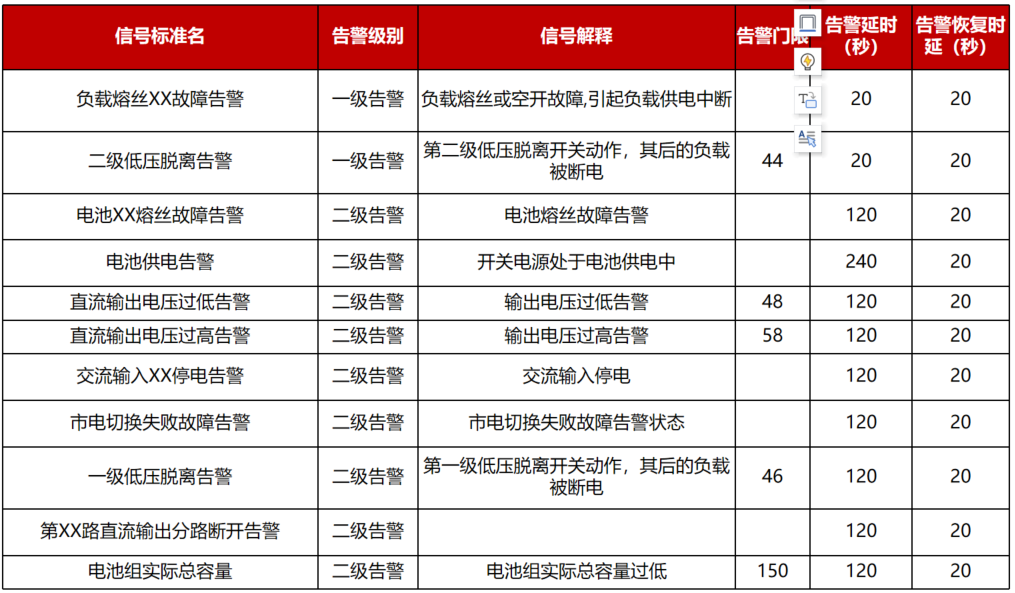
9.4 Important Alarms for Switching Power Supply
Definitions and signal interpretations of important alarms for switching power supply and delay mechanisms:
10
Access Specifications for Intelligent Air Conditioning
10.1 Basic Knowledge of Intelligent Air Conditioning
Air conditioners generate cold and warm air based on the principle that liquid evaporation absorbs heat from the surroundings (making the surroundings cooler), while gas liquefaction releases heat to the surroundings (making the surroundings warmer). Machine room air conditioning is generally divided into large precision air conditioning and small air conditioning. Precision air conditioning is usually installed in core machine rooms, while small air conditioning is generally installed in modular rooms and base stations to regulate the temperature and humidity of the machine room, divided into cabinet and wall-mounted types.
10.2 Functions and Roles of Intelligent Air Conditioning
Intelligent air conditioning is an air conditioning system with automatic temperature adjustment capabilities. The intelligent air conditioning system can analyze, judge, and automatically activate cooling, heating, dehumidification, and air purification functions based on the signals from temperature, humidity, and air cleanliness sensors installed in the machine room according to pre-set indicators and external climate conditions.
10.3 Monitoring Items for Intelligent Air Conditioning
Telemetry: Return air temperature
Remote Signal: Abnormal operation, compressor current abnormality, AC
Remote Adjustment: Operating temperature setting, operating mode setting
Remote Control: Air conditioning on/off
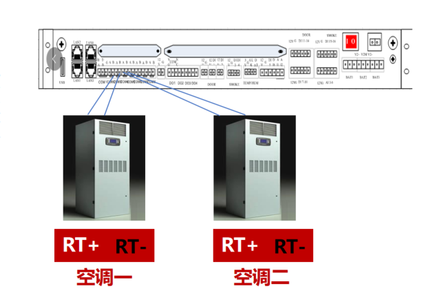
10.4 Intelligent Air Conditioning FSU Wiring Ports
● Device Type: Intelligent Air Conditioning.
● Measurement Points: Four remote.
● Implementation Method: Monitoring module built into the intelligent air conditioning.
● Interface Type: R485 intelligent interface.
11
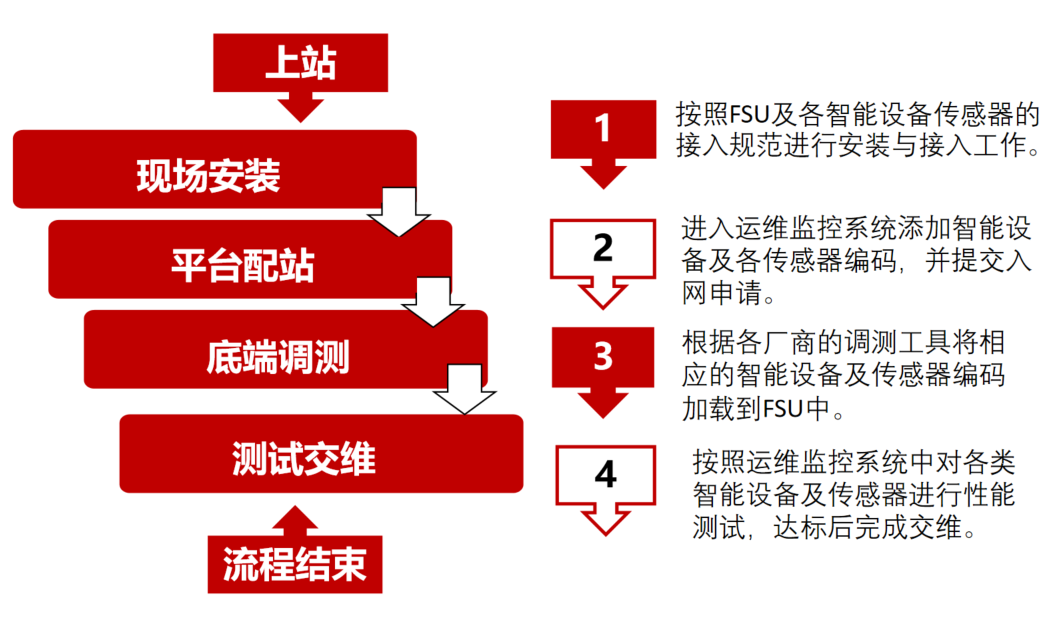
Device Online Installation Process

Editor: Yang Yue
Proofreader: Cui Zhenzhou
Reviewer: Song Ruifeng
Supervising Reviewer: Li Xin
Welcome to reprint, please indicate the source
EXTEND READ | Previous | Read |

National Service Hotline | 400-629-8080