Insights on AHB Bus Learning
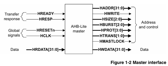
The AMBA 3 AHB-Lite protocol is designed for high-performance synthesizable designs, supporting a single bus master and providing high bandwidth operations. It features burst transfers, single clock edge operations, non-tristate implementations, and configurable data bus widths from 64 bits to 1024 bits, making it suitable for connecting internal storage devices, external storage interfaces, and high-bandwidth peripherals. Low-bandwidth peripherals are typically connected to the APB bus through an APB bridge. The AHB-Lite system mainly consists of a master (which initiates read/write operations and provides address and control information), slaves (which respond to transfers and are selected by the HSELx signal, providing status feedback), decoders (which decode addresses and provide slave selection signals), and multiplexers (which route the read data and response signals from slaves to the master). The transfer is divided into an address phase (single HCLK cycle) and a data phase (which may include wait states controlled by HREADY), with slaves providing feedback on the transfer status through the HRESP signal, indicating success, failure, or wait states.
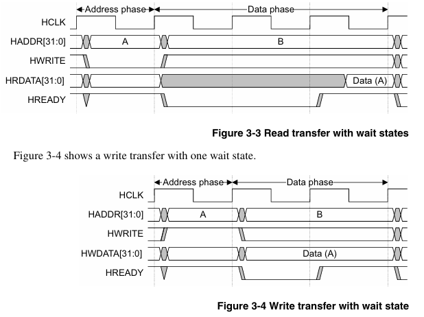
During my study of the AMBA 3 AHB-Lite protocol, I gained a clearer understanding of the basic transfer mechanisms through the AHB master 32-bit read single and write single code with wait states: the single transfer (SINGLE burst, HBURST [2:0] is b000) is the most fundamental transfer type, characterized by the separation of the address phase and the data phase. The introduction of wait states is implemented through the HREADY signal—when HREADY is LOW, the data phase is extended, requiring the master to precisely control the timing relationships of the signals during design. For read single (with wait), it is essential to note that when HWRITE is LOW, after the master drives the address, it must wait for the slave to provide feedback on the transfer status via HREADY. During this time, HRDATA must provide valid data in the final cycle when HREADY is HIGH, ensuring that the address and control signals remain stable during the address phase and can respond to the LOW state of HREADY to extend the data phase. For write single (with wait), when HWRITE is HIGH, HWDATA must remain stable throughout the entire data phase (including wait cycles) until HREADY is HIGH to complete the transfer, which requires the driving logic of HWDATA in the code to be linked with the state of HREADY.