How PLC Controls Stepper Motors
1. Introduction
In the field of modern industrial automation control, the combination of PLC (Programmable Logic Controller) and stepper motors is widely used. Stepper motors have advantages such as precise position control, good reverse control, and stable speed control. As a reliable controller, PLC can provide precise pulse signals for stepper motors, achieving accurate control. This article will detail the principles, wiring methods, programming points, and application examples of PLC controlling stepper motors.
2. Principles of PLC Controlling Stepper Motors
1. Working Principle of Stepper Motors
– A stepper motor is an actuator that converts electrical pulses into angular displacement. When the stepper driver receives a pulse signal, it drives the stepper motor to rotate a fixed angle (called the “step angle”) in the set direction. By controlling the number of pulses, the angular displacement can be controlled to achieve accurate positioning; simultaneously, by controlling the pulse frequency, the speed and acceleration of the motor can be controlled to achieve speed regulation.
2. Connection between PLC and Stepper Motors
– The connection between PLC and stepper motors is usually made by connecting the output port of the PLC to the input port of the stepper motor driver via connecting cables. The output port of the PLC outputs a pulse signal of a certain amplitude, which drives the stepper motor’s driver, thereby controlling the rotation of the stepper motor.
3. Wiring Methods for PLC Controlling Stepper Motors
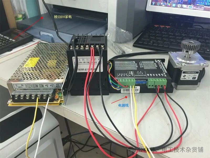
1. Power Supply for Stepper Driver
– According to the specifications of the stepper driver, connect an appropriate power supply to its corresponding power terminals, commonly ranging from DC 24V to 110V, AC 18V to 220V, etc.
2. Connection between Stepper Driver and Stepper Motor
– Connect the phase wires of the stepper motor (usually marked on the motor nameplate) to the corresponding terminals of the stepper driver, typically A+, A-, B+, B-, etc.
3. Control Connection between PLC and Stepper Driver
– The pulse input terminals (PUL+, PUL-), direction input terminals (DIR+, DIR-), and enable input terminals (ENA+, ENA-) of the stepper driver need to be connected to the output ports of the PLC. Generally, PUL-, DIR-, ENA- can be connected to one end of a button, with the other end connected to the power supply 0V, while PUL+, DIR+, ENA+ can be connected to the power supply 24V. Thus, the pulse and direction signals output by the PLC can control the rotation direction and speed of the stepper motor.
– In practical applications, since the output voltage of the PLC may not match the input voltage requirements of the stepper driver, appropriate resistors need to be connected in series at the wiring point for voltage conversion or current limiting to protect the stepper driver and PLC.
4. Programming Points for PLC Controlling Stepper Motors
1. Use of Pulse Output Instructions
– Different brands and models of PLCs have specific pulse output instructions, such as the PLSY instruction for Mitsubishi PLCs and the PTO instruction for Siemens PLCs. These instructions are used to control the PLC to output pulse signals of specific frequency and quantity. For example, the format of Mitsubishi PLC’s PLSY instruction is “PLSY K1000 K10000 Y0”, where the first operand “K1000” indicates a pulse frequency of 1000Hz, meaning that pulses are output through the third operand “Y0” 1000 times per second; the second operand “K10000” indicates the number of pulses, outputting 10000 pulses through “Y0”.
2. Direction Control
– By controlling the direction signal output by the PLC, the forward and reverse control of the stepper motor can be achieved. For example, when the direction signal is high, the stepper motor rotates forward; when the direction signal is low, the stepper motor rotates in reverse. In programming, the output relays or registers of the PLC can be used to control the state of the direction signal.
3. Speed Control
– By changing the pulse frequency output by the PLC, the speed of the stepper motor can be controlled. This can be achieved by setting different pulse frequency parameters in the program or using timer, counter, and other functional modules to change the pulse frequency, thus controlling the speed of the stepper motor.
4. Position Control
– To achieve precise position control of the stepper motor, the required number of pulses must be calculated based on the step angle of the stepper motor, the subdivision settings of the driver, and the mechanical transmission ratio. Then, in the PLC program, the number of pulses can be accumulated or a position counter can be used to determine whether the stepper motor has reached the specified position.
5. Application Example
For a simple automated production line, suppose a stepper motor is needed to control the material’s transport position. First, determine the installation position and transmission method of the stepper motor according to the process requirements of the production line. Then, connect the PLC, stepper driver, and stepper motor according to the wiring methods mentioned above.
In PLC programming, calculate the required number of pulses and pulse frequency for the stepper motor based on the distance and speed requirements of the material transport. For example, if the material needs to be transported 100mm, with a step angle of 1.8° for the stepper motor and a driver subdivision setting of 10, the number of pulses required for one full rotation of the stepper motor is 360° ÷ (1.8° ÷ 10) = 2000 pulses, and the number of rotations required to transport 100mm can be calculated based on the transmission ratio. Assuming a transmission ratio of 1:5, the number of rotations required to transport 100mm is 100 ÷ (2π × r × 5) (where r is the radius of the stepper motor shaft), and then convert the number of rotations to pulses.
Then, using the PLC’s pulse output instructions and position control functions, write a program to achieve precise material transport. When the start signal is triggered, the PLC outputs the corresponding pulse and direction signals to control the stepper motor’s rotation. When the specified position is reached, the PLC stops outputting pulse signals, and the stepper motor stops rotating.
6. Conclusion
PLC control of stepper motors is a precise, reliable, and flexible automation control method, widely used in CNC machine tools, industrial robots, automated production lines, and other fields. With correct wiring and programming, precise control of stepper motors can be achieved to meet various industrial automation control needs. In practical applications, it is necessary to select appropriate PLC models, stepper drivers, and stepper motors based on specific control requirements and equipment parameters, and to perform reasonable programming and debugging to ensure system stability and reliability.
Disclaimer: The articles published by this account are for learning and communication purposes only, with no commercial use. Copyright belongs to the original author, and we pay tribute to the original author. We apologize for any infringement due to the inability to find the original author for some articles that have been reprinted multiple times. If there is any infringement, please inform us, and we will delete it promptly. Please indicate the source when reprinting.
Source: Electrical Engineering Technology Grocery Store