Axial flux motor technology was developed relatively early and theoretically offers advantages such as higher torque density, higher power density, and smaller size. However, due to limitations in materials, processes, and manufacturing technologies (such as complex manufacturing processes, difficulties in coil installation, and even issues like axial movement), its development has been much slower compared to radial flux motors. In recent years, the application of rare earth permanent magnet materials and PCB stator technology has driven improvements in the performance of axial flux motors, leading to their widespread application in fields such as new energy vehicles and robotics.
01
Axial Flux Motor

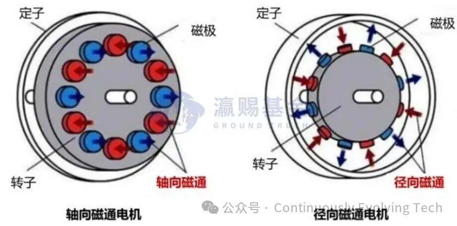
Compared to common radial flux motors, the stator and rotor of axial flux motors are arranged parallel and perpendicular to the rotor shaft. The rotor is mainly composed of permanent magnet materials, while the stator core is made of laminated silicon steel sheets. The stator windings are often produced using printed or wound methods, resulting in a larger winding area that facilitates heat dissipation. More critically, due to the shorter magnetic flux path in axial flux motors (starting from the permanent magnets on the rotor, entering the stator through the air gap, and returning to the rotor to form a closed loop), the magnetic energy utilization per unit volume is higher. Therefore, they can output greater power within the same volume, and the larger rotor diameter allows for higher torque output under the same force.
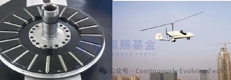
The simplest structure of an axial flux motor (as shown in the figure) consists of only one stator and one rotor. However, the stator must provide a loop for the rotating magnetic poles, so to ensure the stability of the motor rotor, thrust bearings need to be added. Additionally, the magnetic field generated by the rotor will fluctuate within the stator, increasing losses and reducing operational efficiency. Furthermore, this structure is asymmetrical, leading to unbalanced magnetic pull.
In practical applications, a dual-rotor single-stator structure (with the stator in the middle and the rotor’s permanent magnets directly mounted on the casing, forming a structure with two air gaps, which has a larger moment of inertia), a dual-stator single-rotor structure (where the rotor is equipped with permanent magnets and located in the center of the motor, having two symmetrical air gaps, which balances axial magnetic pull and improves mechanical stability while having a smaller moment of inertia than the middle stator structure, with better heat dissipation), and multi-disk composite structures (where multiple rotors and stators are alternately arranged. This structure is complex, but the increase in stator windings can provide higher torque and power density, although it poses challenges for heat dissipation and is very difficult to assemble due to its complexity) are commonly used.
Figure: Axial Flux Motor with Single Rotor and Single Stator Structure
However, regardless of the structure, there are common issues caused by the inclusion of the iron core. For example, heat dissipation issues arise because permanent magnets are sensitive to temperature, and overheating can lead to their failure. The cooling structure of axial flux motors is usually located on the radial sides of the casing, which is effective for cooling the stator core and windings but not as effective for cooling the rotor and permanent magnets. Additionally, when the magnetic flux density in the iron core exceeds its saturation value, the core will no longer effectively conduct magnetism, leading to increased iron losses and decreased motor efficiency. Iron losses account for 20% of total losses, primarily due to hysteresis and eddy current losses in the stator core. Furthermore, there are stability issues at high speeds; due to the axial arrangement of the stator and rotor cores, vibrations and noise can easily occur, affecting the motor’s stability and lifespan.
Thus, the emergence of ironless axial flux motors has become inevitable. On one hand, without an iron core, there are no iron core cogging torques, eliminating a major source of noise. On the other hand, most ironless structures reduce leakage flux by adopting a dual air gap closed magnetic circuit with an intermediate stator structure.
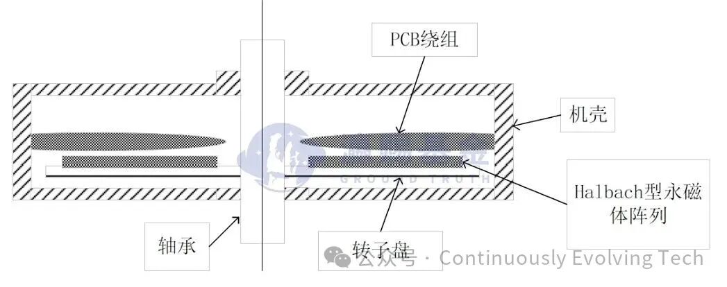
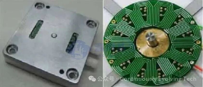
PCB motors are one of the most widely used types of ironless axial flux motors. By using printed circuit boards (PCBs) instead of traditional iron cores and copper wire windings, the overall weight is significantly reduced (as shown in the figure). Additionally, losses in the magnetic flux path are minimized; the ironless design eliminates hysteresis and eddy current losses, significantly improving motor efficiency (typically exceeding 96%). Moreover, the manufacturing process of PCB motors can ensure consistency in wiring through automated production lines, enhancing production efficiency.
02
PCB Axial Flux Motor
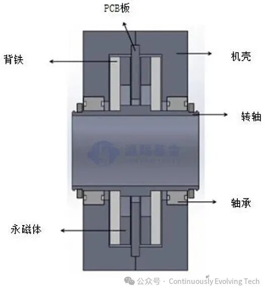
Figure: Cross-Section of Motor Structure
1) Stator
PCB windings differ from wire-wound windings in that wire-wound windings require manual or mechanical winding, and their structure and shape are relatively fixed, making it difficult to achieve high levels of customization and optimization. Additionally, the processing cost of wire-wound windings is relatively high, and issues such as coil sagging and end connections can easily occur during processing. In contrast, PCB windings are directly etched onto the PCB, creating a rotating magnetic field driven by current to rotate the rotor. Under PCB windings, the shape and architecture of the coils are flexible, and the PCB windings can be directly fixed to the motor casing. In special scenarios, the requirements for small size (including thickness) and lightweight can be met.
Figure: Motor Prototype and PCB Windings
In terms of processing technology, the line width, spacing, and copper foil thickness of the windings all affect motor performance. When the current density is constant, thicker copper foil and wider effective conductor line widths can achieve higher output power and efficiency. However, excessively thick copper foil can lead to higher eddy current losses, reducing the motor’s output efficiency. Additionally, the thicker the copper foil, the higher the precision required for the processing equipment. Therefore, a balance must be struck regarding copper foil thickness; generally, the maximum copper plating thickness for a single layer of windings is designed to be 0.175mm, and it can be larger in special cases.
For the PCB itself, a multilayer PCB does not necessarily mean higher performance. The main advantages of increasing the number of layers are to reduce electromagnetic interference, improve signal stability and durability, as well as better wiring density, thermal management, and electromagnetic compatibility. However, in PCB axial flux motors, too many PCB layers can increase the thickness of the PCB, increase the air gap length, and subsequently decrease the air gap magnetic flux density (a core indicator affecting motor performance). Additionally, in terms of cost, about one-third of the processing cost of PCBs comes from machine drilling, and too many layers will also increase the overall cost.
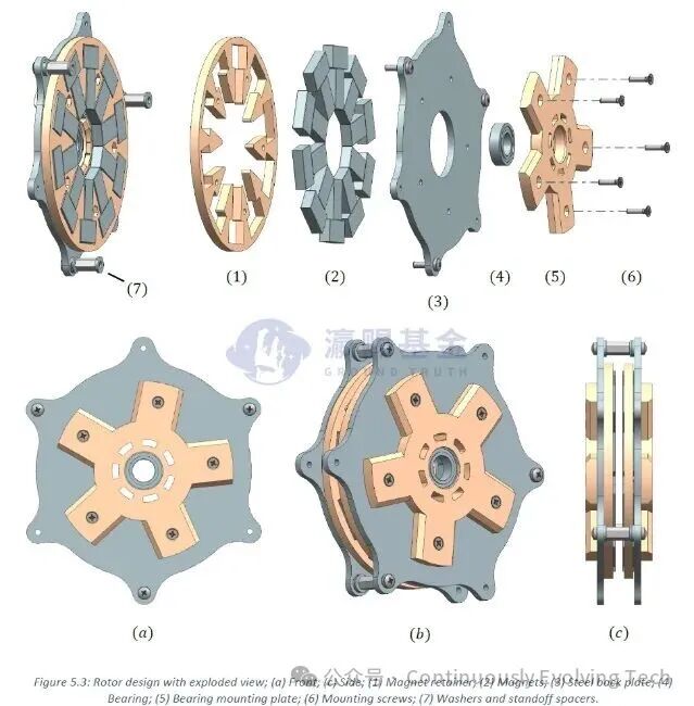
2) Rotor
The quality of magnetic circuit design can be measured by the size of the air gap magnetic density and whether the waveform is sinusoidal, as non-sinusoidal waveforms contain a large number of harmonics, which increase rotor eddy current losses and hysteresis losses. The size of the air gap magnetic density depends on the size of the air gap space, the performance of the permanent magnet material (such as selecting permanent magnet materials with high remanence and magnetic energy product, although they are costly), and the arrangement (such as the common Halbach array scheme).
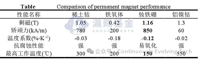
In terms of permanent magnet material selection, the most widely used permanent magnet material is aluminum-nickel-cobalt. Among the four materials shown in the figure, neodymium iron boron has the best overall performance, although its maximum operating temperature is relatively low (magnetic performance can significantly decline at high temperatures (not exceeding 120°) and may even result in irreversible losses). However, considering that axial flux permanent magnet motors adopt a dual-stator single-rotor structure, they have better heat dissipation capabilities, keeping the temperature within a controllable range. Therefore, neodymium iron boron is currently the most widely used. It is worth noting that due to the poor oxidation resistance of neodymium iron boron, protective layers need to be used in practical applications. Finally, after processing the permanent magnets, they are uniformly adhered to the back iron using specific adhesives, forming the rotor.
Table: Comparison of Permanent Magnet Performance
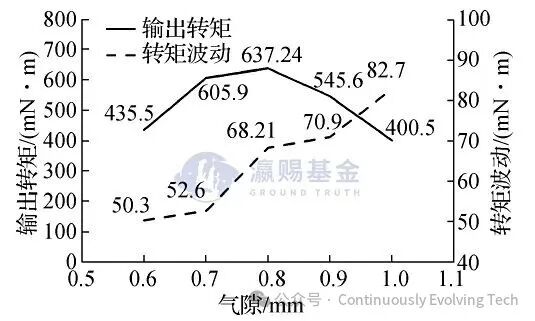
For the air gap length, it is equal to the thickness of the PCB stator winding disc plus the sum of the single-sided air gap lengths between the stator winding and rotor disc body multiplied by 2. If the air gap is too large, the torque output will decrease and torque fluctuations will increase (as shown in the figure), and it will also increase the motor size and require more permanent magnet material, thus raising costs. If it is too small, there may be physical contact between the stator and rotor. Once the air gap length is determined, the thickness of the magnetic steel can also be determined; generally, the ratio of magnetic steel thickness to air gap length should be between 1.2 and 1.6.
Figure: Impact of Different Air Gaps on Output Torque
03
Typical Applications of PCB Motors

Currently, PCB axial flux motors are used in applications with space constraints and high lightweight requirements, such as artificial hearts, robotic joints, and eVTOL aircraft.
In 2020, Anhui Yunyi Aviation Technology Co., Ltd. conducted its first flight test at Luogang Airport in Hefei, Anhui, using an axial flux motor as the drive motor. This was China’s first self-developed all-electric rotorcraft. The aircraft’s two power sources are supplied separately; the drive power rotates the tail of the aircraft, allowing it to taxi, while the pre-rotation power supplies the pre-rotation motor to spin the rotor, generating lift. The aircraft then accelerates and climbs, ultimately taking off.
Figure: Anhui Yunyi Aviation Technology Co., Ltd. Electric Rotorcraft
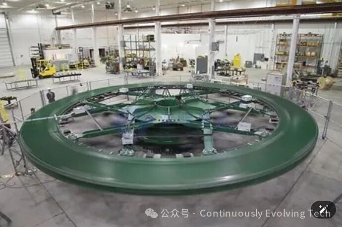
In the wind power generation field, there are also cases utilizing the high torque characteristics of PCB motors. For example, in 2012, Boulder Wind Power (BWP) recognized the potential of PCB stator motors in wind power generation and began efforts to increase the rated power of PCB stator motors to the megawatt (MW) level, with operating voltages reaching up to 600V.
Figure: PCB Stator in Wind Turbines
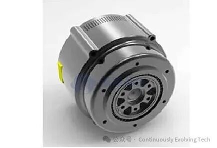
In the robotics field, the application of axial flux motors is also a necessary direction. The axial field integrated electric drive joint developed by Shenzhen Xiaoxiang Electric, as shown in the figure, has dimensions of 90*100mm, integrates a 2-stage reducer and motor driver, with a peak power of 600W, peak output torque of 150N.m, maximum output speed of 200rpm, and a total weight of 1.2kg. This motor features high torque density and fast response speed, with high integration, making it directly applicable to quadruped robots.
Figure: Xiaoxiang Electric Axial Field Integrated Electric Drive Joint
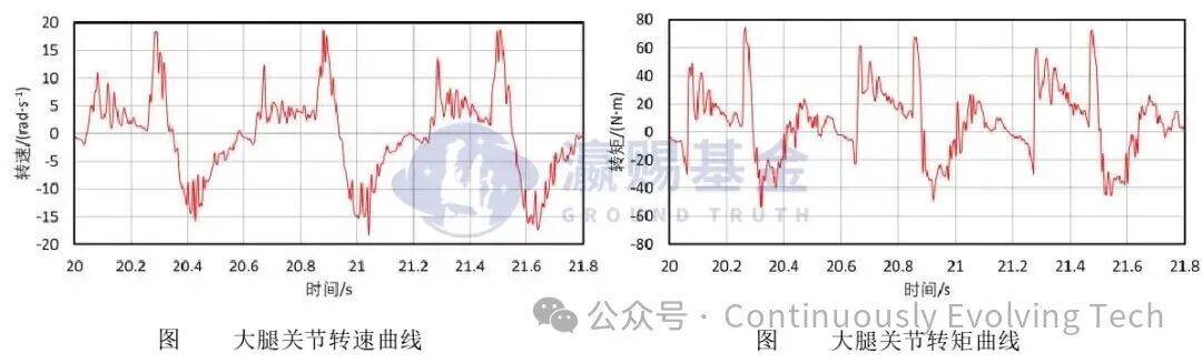
For quadruped robots, since the drive joints undergo frequent swinging, the electric drive joints need to have a fast response speed. When the thigh joint reaches its maximum torque, the rate of speed change is also very high. Moreover, the peak torque output of the thigh joint can reach up to 80N.m within a cycle (as shown in the figure), thus the motors within the electric drive joints of quadruped robots must possess characteristics of fast response and high torque density.
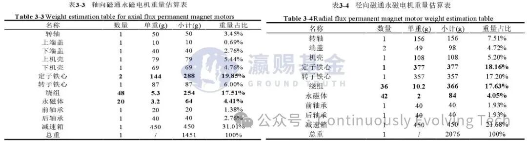
As shown in the figure, under the same material and output performance constraints (rated torque of 2.7N.m), the weight of the axial flux motor is significantly lower. In terms of torque density (the rated torque output per unit effective mass of the motor), which is calculated as the rated torque of the motor divided by the effective mass of the motor (the main components involved in electromechanical energy conversion, including the motor stator, motor windings, and permanent magnets), it can be calculated that the torque density of axial flux permanent magnet motors is 36.5% higher than that of radial flux permanent magnet motors. If it is a PCB motor, removing the iron core and reducing the amount of copper wire will further increase the torque density.
Regarding response speed, since the magnetic flux direction of axial flux motors is parallel to the rotation axis, while that of radial flux motors is perpendicular to the rotation axis, the magnetic flux path of axial flux motors is shorter and more direct, reducing energy losses during transmission, thus theoretically allowing for faster response speeds. Therefore, considering the advantages in volume, torque density, and response speed, PCB axial flux motors have greater application prospects in the robotics field.
Risk Warning:
This document is not a promotional material for funds, but serves as one of the customer service matters for the funds under our company. Any information provided in this document is for the reader’s reference only and does not constitute a necessary basis for future investment decisions regarding the funds managed by our company, nor does it constitute any substantive investment advice or commitment to the reader or investors. Funds carry risks, and investments should be made cautiously. The opinions contained in this document are solely those of the date of issuance, and at different times, Yingci Fund may issue opinions inconsistent with those contained herein. Without the written permission of Yingci Fund, no institution or individual may forward, reproduce, copy, publish, or quote this document in any form.
END

Yingci Fund
Embracing Diversity
Ying in Net Value
CopySearchShareCollectStrike Through
People