 Search WeChat
 Technical TrainingProject Analysis
Project analysis requires a comprehensive examination of the production process, working environment, hardware requirements, and control requirements of the project.
This work is the foundation of the entire system design. If the preliminary project analysis is inadequate, it will lead to inaccurate hardware selection later, resulting in project delays.
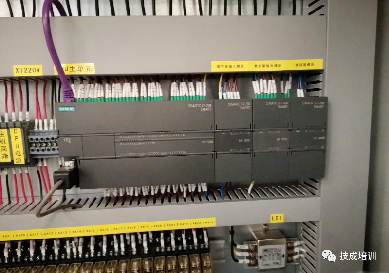
1. Project Analysis
Engineers must first analyze the project, including the control processes and types of control for each process, and anticipate potential issues that may arise throughout the project.
(1) Analyze control processes. When analyzing control processes, it is recommended to draw relevant control flow diagrams, clearly marking the content of each step and the conditions for moving to the next step.
(2) Analyze control types and estimate the parameters required for PLC selection. Generally, PLCs are suitable for four types of control: sequential control, process control, motion (or position) control, and network communication. After analyzing control requirements and based on the drawn control flow diagrams, engineers should classify the control types of each control process, and combine control types according to the complexity of the project. Therefore, accurately analyzing each step’s control type in the early stages will aid in accurate selection and problem estimation.
While analyzing project control types, engineers must also estimate the important parameter values required for PLC selection. For instance, in sequential control, the number of I/O points; if using encoders, calculate the output pulse frequency based on the encoder parameters, and convert it into the PLC’s high-speed counting pulse frequency. Similarly, in process control, consider the number and accuracy of analog quantities, and in motion control, the PLC’s response speed to feedback signals from servo drives and the number of high-speed pulse outputs from the PLC, as well as whether the selected PLC supports the corresponding network type during network communication.
2. Estimating Potential Issues
Estimating potential issues is one of the more challenging aspects of engineering analysis. This requires engineers to have a solid understanding of the working environment on-site and the control challenges of the entire project, as well as to anticipate possible emergencies and hazards.
(1) Understanding the working environment of the equipment. Engineers need to have a comprehensive understanding of the production environment. For example, in a textile machinery environment, the air humidity is high and vibrations are significant, so the PLC system design must include anti-vibration measures. In a building materials processing plant, the ambient temperature is relatively high, with significant dust and strong static electricity, so engineers must ensure good ventilation for the electrical control cabinet while also implementing dust and static electricity protection.
The understanding of the equipment working environment is not limited to physical conditions; with deeper PLC applications, personnel factors must also be considered. For instance, if the quality of the equipment operators is low, a more simplified equipment operating interface needs to be developed.
(2) Anticipating project challenges. Anticipating project challenges involves grasping the core issues of the project. For example, the control core of jet weaving machines is how to quickly and orderly control solenoid valves, using the friction of compressed air to pull the weft yarn through the shuttle, completing the weaving operation, which requires the PLC to have a very fast response speed. Once the project challenges are identified, engineers can select the PLC based on these challenges. From the overall project perspective, the challenges of the project define the characteristics of the system design and guide the PLC selection.
(3) Preliminary estimation of project hazards. During the early design phase, engineers need to anticipate potential hazards that may arise in the project. For instance, in sequential control or motion control, safeguards against erroneous actions when debugging equipment; in process control, whether there are high pressures, high temperatures, or toxic substances during testing and the corresponding protective measures. Estimating hazards during the early design phase helps enhance engineers’ safety awareness.
PLC Hardware Selection
The selection of PLCs is based on the preliminary project analysis and the anticipated project challenges, following several key principles.
1. Special First, General Second Principle
Based on engineering experience, the factors limiting PLC selection in most engineering projects concentrate on several key points, so the principle of special first, general second should be followed.
The term ‘special’ refers to the specific control requirements of the project; different control types have different primary limiting factors. For instance, in sequential control, the CPU program capacity and I/O point expansion capability are the main factors for PLC selection. In process control, the number of analog quantities and their accuracy are the starting point for selection. In simpler motion control, the PLC needs to receive position signals from field encoders and correspondingly send out pulses at a certain frequency to control the servo motor. Therefore, the PLC’s data processing speed, its ability to receive high-speed pulses at input, and its ability to send high-speed pulses at output will become the primary factors in PLC selection. In large composite projects, different PLCs need to be networked, making the supported network types a primary factor in PLC selection.
Engineers should arrange the different control requirements from special to general according to the core needs of the project. This approach will yield better results and reduce the overall difficulty of the project.
2. Bottom-Up Principle
The purpose of the bottom-up principle is to maximize the cost-effectiveness of PLC selection. Currently, most manufacturers’ PLC products are divided into several series. When engineers select PLCs, they should follow the selection order from special to general, starting with the lowest model PLC and comparing performance parameters one by one. When a model does not meet the requirements, consider a higher model. Repeat this process until all selected PLC models meet the requirements. If selection is done from top to bottom, it may lead to wasted PLC functions, resulting in over-specification.
3. Selection of PLC Digital Input/Output Units
PLC’s digital input points are used to receive level signals from field sensors, while the outputs are driven by internal control signals to control external loads.
(1) Selection of digital input terminals. Currently, PLC input points are all transistor inputs, and users only need to select based on the estimated number of input points. However, it is important to note that due to different wiring types for PLC terminals, there are NPN and PNP input methods. This means that the input terminal is effective based on either low-level or high-level signals. Once the wiring type of the input terminal is determined, sensors of the same type must be used; NPN and PNP sensors cannot share the same PLC input terminal.
Currently, the majority of PLC input terminals use a DC 24V input voltage. If sensors with different voltage specifications need to be connected to the PLC, relays should be used for appropriate isolation, ensuring that the signals entering the PLC input terminals are DC 24V voltage.
(2) Selection of digital output terminals. The types of PLC digital output points are mainly relay-type outputs and transistor outputs.
① Relay output type. Relay outputs have good load capacity, can withstand high overvoltage and overcurrent for short periods, and provide strong isolation. However, due to the mechanical contacts inside the relay, their lifespan is limited, so they should only be used in applications that require lower action frequencies and do not need high-speed pulse outputs.
② Transistor output type. Transistor outputs control the opening and closing of output terminals by controlling the conduction of internal transistors. Since there are no mechanical contact structures inside, transistor output contacts have a longer lifespan, higher action frequency, and are less prone to damage, but they have poorer load capacity.
(3) Considerations for selecting digital output terminals. Similar to input terminals, transistor output terminals are also divided into NPN and PNP types. Once the model is determined, loads must be connected according to the same wiring method.
In practice, it is recommended that engineers often use transistor output PLCs and use relays at the output terminals to connect external loads, providing electrical isolation for downstream load devices. This combination leverages the long lifespan of transistors and the strong load capacity of relays. If electrical faults occur, the PLC output terminals will be protected by the isolation relay and will not be damaged, requiring only the replacement of the damaged relay. However, if the relay output PLC terminals are damaged, the damaged terminals cannot be repaired.
4. Built-in First, Expansion Second Principle
With the continuous evolution of PLCs, especially the enhancement of functions in small machines, many expansion module functions, such as analog functions and communication functions, are already built into PLCs. Therefore, when selecting, it is advisable to choose PLCs with more built-in functions, which reduces costs, saves control cabinet space, and simplifies setup and programming workload.
5. Grasping the Redundancy in PLC Selection
Due to preliminary estimates, on-site construction changes, and later maintenance upgrades, PLC selection must consider a certain redundancy. For smaller engineering controls, a redundancy range of 20% is appropriate; for larger engineering controls, 5% to 10% is suitable. Other redundancy issues, such as analog quantities, communication, and bus functions, should be flexibly managed by engineers based on the on-site hardware configuration. If control functions are all built into the PLC, then a higher-level standalone PLC should be replaced; if control functions are achieved through expansion modules, only the corresponding modules need to be updated when considering redundancy.
PLC Programming Key Points
(1) Allocate program segments based on control flow diagrams.
Based on the preliminary control flow diagram, decompose the control program into different segments, which can clarify the overall structure of the program and facilitate later debugging. If the project is complex, segmenting the program allows several programmers to work simultaneously on programming and debugging, improving overall programming efficiency.
(2) Create I/O tables and memory tables.
Creating an I/O table assigns addresses to each input/output point and provides annotations to avoid confusion during programming. Creating a memory table assigns PLC memory addresses to intermediate variables in the program and provides annotations for easier reference during programming.
(3) Simplify programming.
Programmers, familiar with the PLC instruction system, can greatly reduce programming workload and save PLC memory space by proficiently using advanced instructions, helping to better utilize PLC functions.
(4) Clear annotations.
To facilitate later debugging, programmers should clearly annotate each relevant point in the program, including the purposes of special instructions used. Good program readability lays the foundation for later project maintenance and upgrades.
PLC Program Debugging Methods
The debugging of PLC application programs can be divided into two steps: simulation debugging and online debugging.
1. Simulation Debugging
Simulation debugging refers to debugging based on the display states of the corresponding LEDs on the digital I/O units without connecting output devices.
After designing the control program, simulation debugging is generally performed first. Some PLC manufacturers provide simulation software that can run on computers to replace PLC hardware for program debugging, such as Omron’s CX-Simulator software, which pairs with CX-Programmer. During simulation, based on system function requirements, certain input component bits can be forced to ON or OFF, or data in certain components can be modified to monitor whether the system functions can be correctly implemented.
When debugging the program by connecting the PLC hardware, small switches and buttons connected to the input terminals can be used to simulate actual input signals to the PLC, such as issuing operational commands or simulating actual feedback signals, like the opening and closing of limit switch contacts. By observing the corresponding LEDs on the digital output units, one can check whether the output signals meet the design requirements.
The main task of debugging the sequential control program is to check whether the program runs according to the specifications of the sequential control diagram. Specifically, when a certain transition is realized, whether the active step state changes correctly, whether all preceding steps become inactive, whether all subsequent steps become active, and whether the loads driven by each step change accordingly. During debugging, various possible scenarios should be fully considered, and each different operating mode of the system, each branch in the sequential control diagram, and all possible progress routes should be checked one by one without omission. When issues are found, the program should be modified timely until the relationships between input and output signals meet the requirements under all possible conditions. If certain timer or counter set values in the program are too large, to shorten debugging time, they can be reduced during debugging and reverted to their actual set values after simulation debugging.
In conclusion, simulation debugging is a very important part of the entire program design process, allowing for a preliminary check of the program’s actual effects. Simulation debugging and program writing are inseparable; many program functions are continuously modified and refined during debugging. Simulation debugging can be conducted in a laboratory or on-site. If performed on-site, the PLC system should be isolated from on-site signals, and the external power supply to the I/O units should be cut off to prevent unnecessary losses.
2. Online Debugging
Online debugging refers to the process of installing the PLC in the control cabinet, connecting input components and output loads, and running the control program for overall debugging.
During simulation debugging, the design and production of the control cabinet, as well as the installation and wiring of other hardware outside the PLC, can also proceed simultaneously. After completing the internal wiring of the control cabinet, wiring tests should be conducted. One can simulate external digital input signals on the terminal of the control cabinet or operate buttons and command switches on the control cabinet panel to observe whether the state changes of the corresponding PLC input points are correct. By using a programmer or programming software, PLC output points can be forced to set or reset, and one can observe whether the corresponding PLC loads (such as external relays, contactors, etc.) operate normally or whether the state changes of output signals on the control cabinet terminal are correct.
For systems with analog inputs, standard input signals can be provided to transmitters. By adjusting potentiometers on the unit or parameters in the program, the relationship between the analog input signals and the converted digital signals can be made to meet the requirements.
After the control cabinet is installed on-site and the internal wiring tests are completed, external input components and actuators should be connected to the PLC. The PLC should be set to run mode, and the control program should be executed to check whether the control system meets the requirements.
During debugging, potential hardware issues in the PLC system and problems in ladder diagram design may be exposed. These issues should be resolved on-site until all requirements are fully met. After completing all debugging, a period of trial operation should also be conducted to verify the reliability of the system.
Disclaimer: This article is reprinted from the internet, and the copyright belongs to the original author. If there are any copyright issues, please contact us in a timely manner to delete it. Thank you!
HISTORY/Previous Recommendations
Complete Question Bank for 2022 Junior Electrician Exam (with Answers)
3 Must-Have Tools for Electricians, Easily Accessible via WeChat!
【Collection】 The “Path” for a Decade-Long Electrician, Secrets to Earning Over 10,000 Monthly!
Which of the Five Major Electrical Drafting Software (CAD, Eplan, CADe_simu…) Do You Choose?
The Latest Electrical CAD Drawing Software, with an Ultra-Detailed Installation Guide!
The Latest Electrical Drawing Software EPLAN, with an Ultra-Detailed Installation Guide!
Common Issues for Beginners Using S7-200 SMART Programming Software (with Download Links)
Comprehensive Electrical Calculation EXCEL Sheets, Automatically Generated! No Need to Seek Help for Electrical Calculations!
Bluetooth Headphones, Electrician/PLC Introductory Books Given Away? Come and Claim Your Electrical Gifts!
Basic Skills of PLC Programming: Ladder Diagrams and Control Circuits (with 1164 Practical Cases of Mitsubishi PLC)
Still Can’t Understand Electrical Diagrams? Grab the Basics of Electrical Diagram Recognition and Simulation Software, Quickly Get Started with Theory and Practice!
12 Free Electrician Video Courses, 10GB of Software/E-Book Materials, 30 Days of Free Live Electrician Classes Given Away!
Don’t Forget to Like + Read!
 Click “Read Original” to Learn PLC/Electrician Courses for Free