 Accumulated FPGA Knowledge Points (19)
How to Free FPGA Boards from JTAG Cable Constraints and Achieve Remote Programming Updates
To free FPGA boards from JTAG cable constraints and achieve remote programming updates, the core idea is to “enable the FPGA system to receive update files over the network and write them into the configuration Flash”. Below is a detailed analysis, providing key design ideas and code examples.
🔄 Core Architecture for Remote Updates
A typical remote update system usually includes the following core components, and its workflow can be summarized in the diagram below:
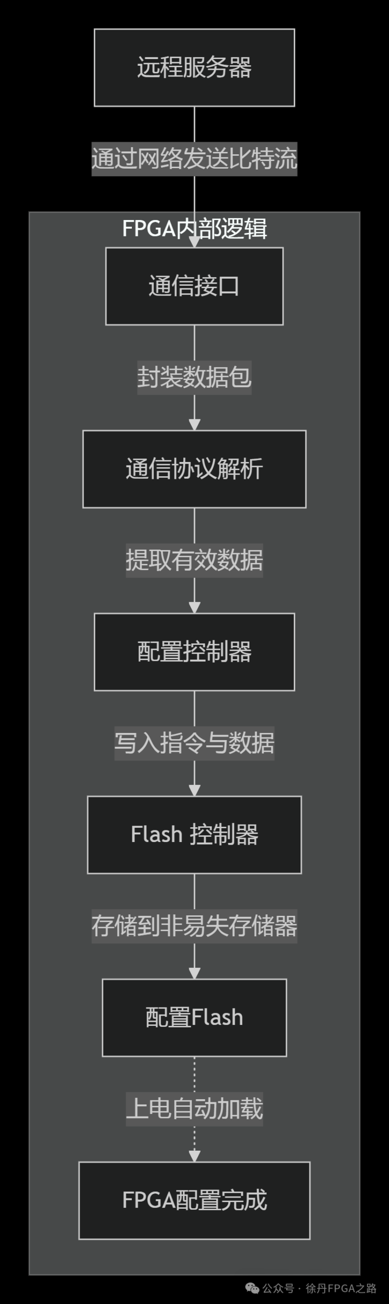
The core components arecommunication interfaces, protocol parsing, configuration (Flash) controllers, and non-volatile configuration memory (such as SPI Flash) working together. The FPGA logic part typically requires a soft-core processor (such as MicroBlaze) to run complex protocol stacks and control processes.
🌐 Ethernet Remote Update Solution
Ethernet is one of the most commonly used methods for achieving remote updates, relying on the TCP/IP protocol stack for reliable data transmission.
System Architecture Design
- Hardware Platform must include Ethernet PHY chips and interfaces.
- Logic Design integrates a soft-core processor (such as MicroBlaze) within the FPGA, equipped with an Ethernet MAC IP core.
- Storage Association connects the soft-core to external configuration Flash via an SPI controller IP (such as Xilinx’s AXI Quad SPI).
Key Code Example (MicroBlaze C Program)
The following code snippet demonstrates the key operations for writing to Flash via SPI using the MicroBlaze soft-core:
#include "xil_io.h"
#include "xspi.h"
// Assuming using Xilinx SPI driver
// Main update function
int update_fpga_via_ethernet(XSpi* SpiInstancePtr) {
    // 1. Receive and verify file
    if (receive_file_from_ethernet(&bitstream) != SUCCESS) {
        xil_printf("Error receiving file\n");
        return XST_FAILURE;
    }
    // 2. Erase Flash
    if (erase_entire_flash(SpiInstancePtr) != SUCCESS) {
        xil_printf("Flash erase failed\n");
        return XST_FAILURE;
    }
    // 3. Write new data
    if (write_bitstream_to_flash(SpiInstancePtr, &bitstream) != SUCCESS) {
        xil_printf("Flash write failed\n");
        return XST_FAILURE;
    }
    // 4. Optional: Verify written data
    if (verify_flash_content(SpiInstancePtr, &bitstream) != SUCCESS) {
        xil_printf("Flash verify failed\n");
        return XST_FAILURE;
    }
    xil_printf("FPGA update successful. Reboot to load new image.\n");
    return XST_SUCCESS;
}
// Example: Function to erase Flash (implementation depends on specific Flash chip model)
int erase_entire_flash(XSpi* SpiInstancePtr) {
    u8 WriteEnableCmd = 0x06; // Send write enable command
    u8 BulkEraseCmd = 0xC7; // Bulk erase command
    XSpi_Transfer(SpiInstancePtr, &WriteEnableCmd, 1); // Wait for write enable to complete
    XSpi_Transfer(SpiInstancePtr, &BulkEraseCmd, 1); // Wait for erase to complete
    return XST_SUCCESS;
}
Key Points of Communication Protocol
The PC (host) and the soft-core within the FPGA require a set of custom application layer protocols to ensure the reliability of the update process. A typical protocol interaction flow is as follows:
// Example: Simplified communication flow between PC and MicroBlaze
PC -> FPGA: Send reset command [0x55, 0xAA,...] // Trigger FPGA to prepare for update
FPGA -> PC: Reply reset complete [0xAA]
PC -> FPGA: Send file length [0x55, 0xAA, 0x01, 0x01, len_low, len_mid, len_high]
FPGA -> PC: Confirm file length [0xAA, len_low, len_mid, len_high]
PC -> FPGA: Send erase command [0x55, 0xAA, 0x02, 0x02]
FPGA -> PC: Erasing in progress... [0xAA] (sent multiple times)
FPGA -> PC: Erase complete [0x55]
PC -> FPGA: Start transferring data block [0x55, 0xAA, 0x03, 0x03, data...]
FPGA -> PC: Data write progress [0xAA] (sent multiple times)
PC -> FPGA: Send write complete command [0x55, 0xAA, 0x04, 0x04]
FPGA -> PC: Verification result [0x55] (success) or [0x7E] (failure)
📡 Fiber and FC Protocol Update Solution
For applications with high bandwidth and reliability requirements (such as radar and high-speed data acquisition), fiber optics and FC (Fibre Channel) or Aurora protocol (a lightweight link layer protocol provided by Xilinx) can be used.
System Architecture Design
- Core Protocol uses Xilinx’s Aurora 8B/10B IP core to establish a high-speed serial link.
- Data Processing within the FPGA logic receives complete update file packets through large-capacity buffers like DDR memory, and then writes to Flash.
- Reliability Assurance adds a handshake retransmission mechanism at the application layer to ensure the reliability of high-speed data transmission.
Key Logic Design (Verilog Example)
The following is a simplified logic example for Aurora data reception and forwarding:
module aurora_update_engine (
    input  wire         user_clk,
    input  wire         aurora_rx_valid,
    input  wire [63:0]  aurora_rx_data, // Other Aurora user interface signals...
    output reg          flash_spi_cs,
    output reg          flash_spi_sclk,
    output reg          flash_spi_mosi);

// State machine definition
localparam STATE_IDLE   = 3'b000;
localparam STATE_RECV   = 3'b001;
localparam STATE_WRITE  = 3'b010;
// More states...

reg [2:0] current_state;
reg [63:0] data_fifo [0:1023]; // Instantiated data buffer
reg [15:0] wr_ptr;

// Data reception state machine
always @(posedge user_clk) begin
    case (current_state)
        STATE_IDLE: begin
            if (aurora_rx_valid && is_start_of_frame(aurora_rx_data)) begin
                current_state <= STATE_RECV;
                wr_ptr <= 0;
            end
        end
        STATE_RECV: begin
            if (aurora_rx_valid) begin
                // Store data in buffer
                data_fifo[wr_ptr] <= aurora_rx_data;
                wr_ptr <= wr_ptr + 1;
                if (is_end_of_frame(aurora_rx_data)) begin
                    current_state <= STATE_PROC_HEADER;
                end
            end
        end
        // Other states: process header, write to Flash, etc...
    endcase
end

// Helper function: Check frame start/end
function is_start_of_frame;
    input [63:0] data;
    // Determine based on custom protocol, e.g., specific sync header
    is_start_of_frame = (data[63:56] == 8'hFB); // Example
endfunction

// Flash SPI write logic (only a simple framework shown here)
always @(posedge user_clk) begin
    // Based on current state and pointer, send data from data_fifo to Flash via SPI interface
    // ... Specific SPI state machine implementation
end
endmodule
🛠️ Key Steps to Implement Remote Updates
Regardless of the communication method used, achieving reliable remote updates requires following these key steps:
- Generate Configuration Files In Vivado, convert the designed bitstream (.bit file) into an MCS file suitable for Flash programming.
- Build Hardware System Configure the FPGA with a system that includes a processor, communication IP (Ethernet MAC/Aurora IP), Flash controller, and ICAP (Internal Configuration Access Port).
- Develop Firmware and Communication Protocol Write programs for the soft-core to implement file transfer, verification (e.g., CRC32), Flash erasure and programming, and error handling.
- Design a Secure Reboot Mechanism After the update is complete, trigger the IPROG command or reboot the system to allow the FPGA to reload the new configuration from Flash.
⚠️ Important Considerations
- Reliability First The update process must include data verification (e.g., CRC) and write operation verification. To prevent bricking due to update failures, consider a dual boot (Golden/User Image) design.
- Security Considerations Implement authentication for remote update operations and encrypt the transmitted bitstream to prevent unauthorized access and malicious firmware injection.
- Protocol Selection Ethernet is highly versatile and suitable for most applications. Fiber/Aurora is more suitable for high-speed interconnects within and between boards, and for scenarios with strict reliability and latency requirements.
- Flash Model Matching Different brands and models of SPI Flash may have differences in their instruction sets (e.g., write enable, page programming, bulk erase) and timing, so refer carefully to the datasheets.
💎 Summary
The core of achieving remote updates for FPGA is to enable the FPGA system to reliably receive and write configuration Flash over the network. The Ethernet solution is versatile, while the fiber/FC (Aurora) solution has clear advantages in specific high-performance scenarios. The key lies in stable communication, reliable data processing and Flash operations, and comprehensive error recovery mechanisms.