01
Structure of SIB
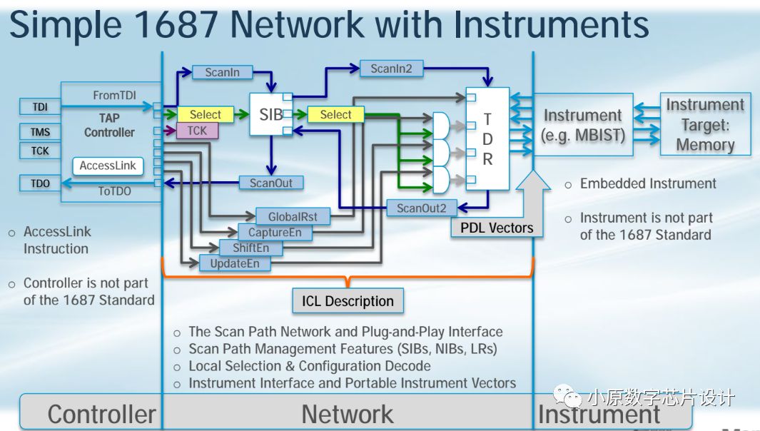
SIB (Segment Insertion Bit) is a fundamental unit of the IEEE 1687 standard specification. Utilizing the characteristics of SIB circuitry, we can achieve plug-and-play and flexible configuration of the IJTAG network. Essentially, SIB is a single-bit TDR. By controlling the two states of SIB being on and off, we can connect this TDR to the TAP network or remove it from the TAP network. We can think of SIB as a bidirectional socket; it can connect to the upper-level SIB and can accept the lower-level SIB. The IJTAG network can support as many levels of SIB as we want to implement. Below is a detailed introduction to the structure and switch states of SIB. First, in the off state, as shown in the figure below, we can shift a 0 into TDI. We activate this TDI through the Select signal, and the 0 propagates backward to the Shift register. To turn off this SIB, we actually need to configure the Update register to bit 0. Therefore, at this point, there is an UpdateEn signal, and we can move the value from the Shift register to the Update register. If we keep the UpdateEn signal low, it means that this SIB and its subsequent network remain off.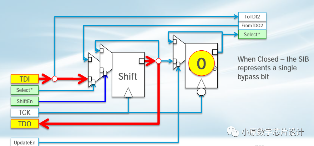
Next is the on state. When the Select signal is 1, the signal from TDI reaches the next level of the network. This network can continue to be a SIB network or a TDR network. At this point, we enable ShiftEn, and the data can be returned to the upper-level TDI or TAP Controller.
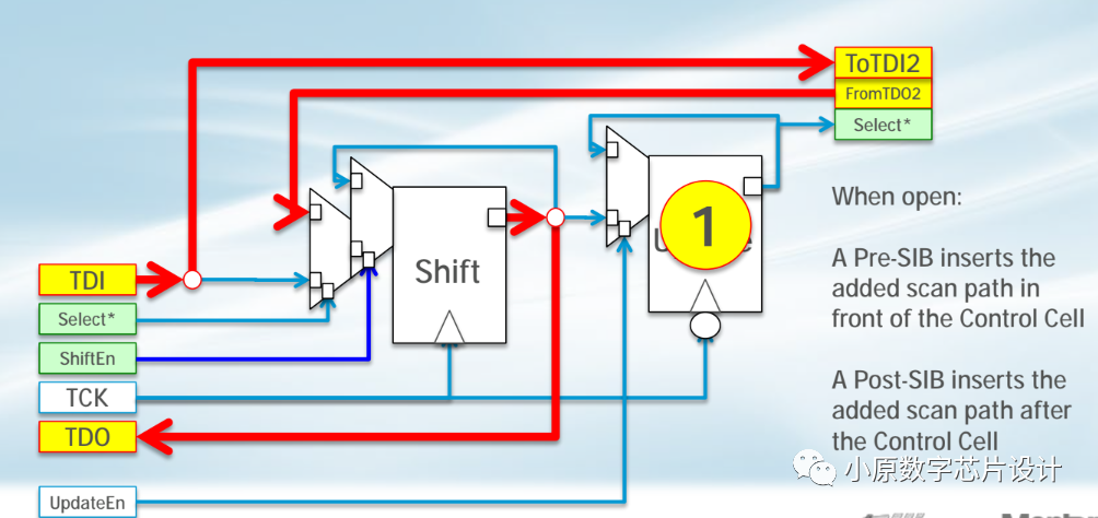
As shown in the figure below, placing SIB into the entire 1687 network, the Select from SIB itself controls the sub-network. It is worth noting that not all TDRs must be attached to SIB; only by introducing SIB does the network become complex and rich. The language used to describe this network is ICL.
02
Mentor Tessent SIB Structure
The diagram below shows the structure of SIB in Mentor Tessent. We can see that the Select signal depends on the Select of the previous layer and also generates a Select for its sub-network. The AND gate in the lower left corner of the figure determines whether the current SIB is selected. If the current SIB is not selected, the sub-network connected to this SIB will also not be selected. If the current SIB is selected, the Update value is used to determine whether the sub-network is selected.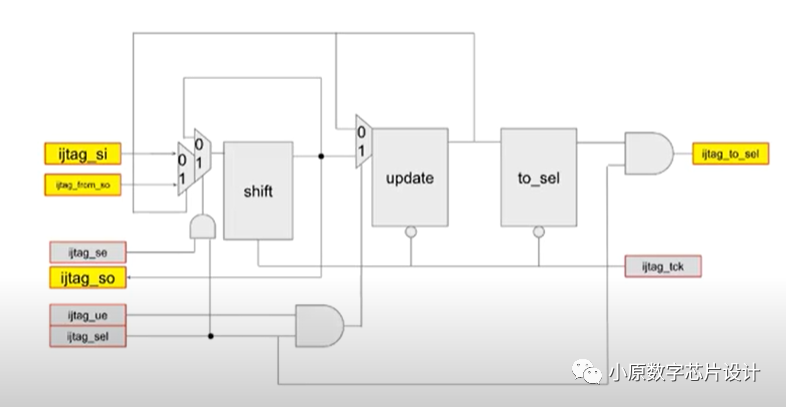 03TAP Controller
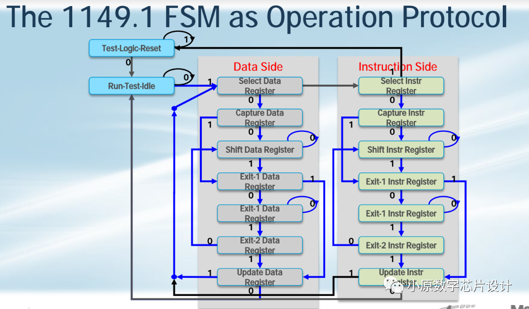
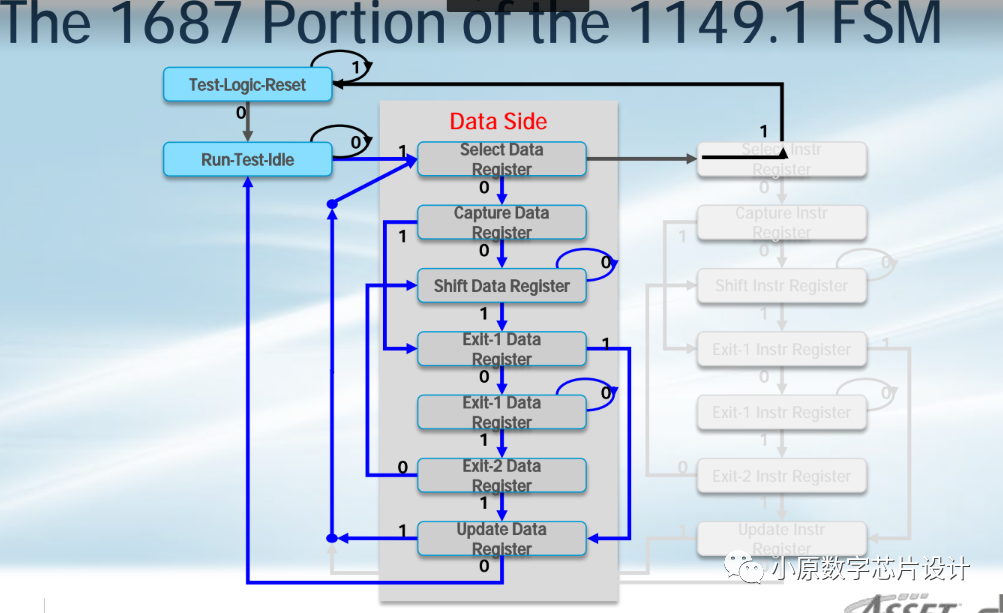
Generally, we will use the TAP Controller from 1149.1 to control the entire 1687 network. As shown in the two figures below, the TAP Controller from 1149.1 consists of two parts: the Data Register and the Instruction Register. Since we do not assign a dedicated Instruction for each IP or TDR in 1687, the Instruction Register is unnecessary. The Instruction is mixed within the Data itself, and during the process of shifting data, the network is also configured.