Power Calculation
According to the literature “Self-sensing Passive RFID: from Theory to Tag Design and Experimentation”, the power received by the tag on the Power-Up LinkPR->T (from reader to tag) and the reader’s received power on the Backscatter Link (Backscatter Link) are theoretically given by the formulas:

 Where:
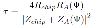 is the power transfer coefficient of the tag antenna.
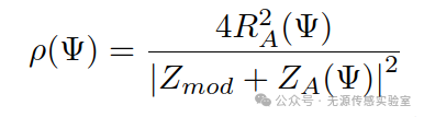 It describes the impact of antenna impedance mismatch on backscatter power. Based on the above formulas, the received power of the tag and reader can be calculated using Matlab (or custom Output Variables in HFSS). Assuming a power frequency of 915MHz, a distance of 2m between the tag and reader, a reader output power of 27dBm, a reader antenna gain of 9dBi, and a tag antenna gain of 0dBi, the power transfer coefficient τ (tau) and the scattering matching factor ρ (rho) are both calculated to be 0.95 (method referenced in【Software Tutorial】HFSS Power Transfer Coefficient Calculation). The reader antenna is circularly polarized while the tag antenna is linearly polarized, thus the polarization matching factor η (eta) = 0.5. The following Matlab code is used for the calculation:
% Input parameters% Operating frequency, in Hzf=915*1e6% Calculate wavelength=c/flamda=3*1e8/f% Input distance between tag and reader, in md=2% Input reader rated output power, in dBmPinput=27% Convert reader output power to WPin=10^(Pinput/10)/1000% Input reader antenna gain, in dBiGReader=9% Convert reader antenna gain to dimensionlessGR=10^(GReader/10)% Input tag antenna gain, in dBiGTag=0% Convert tag antenna gain to dimensionlessGT=10^(GTag/10)% Input power transfer coefficient, previously introduced calculation methodtau=0.95% Input scattering matching factorrho=0.95% Input polarization matching coefficient, when the reader antenna is circularly polarized and the tag antenna is linearly polarized, the matching coefficient is 0.5eta=0.5% Calculate tag received powerPR->T, in WPtag=lamda^2/(4*pi*d)^2*GR*GT*tau*eta*Pin% Convert PR->T to dBmPT=10*log10(Ptag*1000)% Calculate reader received powerPR<-T, in WPReader=lamda^4/(4*pi*d)^4*GR^2*GT^2*rho*eta^2*Pin% Convert PR<-T to dBmPR=10*log10(PReader*1000)It can be concluded that the tag received power PT =-4.9239 dBm, and the reader received power PR =-36.6250 dBm.
Reading Distance Calculation
Further, based on the formula for tag received power, the reading distance of the tag can be derived, which is the distance beyond which the tag chip cannot be activated. Therefore, at the reading distance, the tag’s received power should equal the chip’s threshold power Pth (threshold power, which can be found in the chip datasheet). That is:
 According to the current formula, the distanced is the reading distance of the tag. The following Matlab code is used for the calculation:
% Input parameters% Operating frequency, in Hzf=915*1e6% Calculate wavelength=c/flamda=3*1e8/f% Input reader rated output power, in dBmPinput=27% Convert reader output power to WPin=10^(Pinput/10)/1000% Input reader antenna gain, in dBiGReader=9% Convert reader antenna gain to dimensionlessGR=10^(GReader/10)% Input tag antenna gain, in dBiGTag=0% Convert tag antenna gain to dimensionlessGT=10^(GTag/10)% Input power transfer coefficient, previously introduced calculation methodtau=0.95% Input polarization matching coefficient, when the reader antenna is circularly polarized and the tag antenna is linearly polarized, the matching coefficient is 0.5eta=0.5% Input chip threshold power, in dBmPthreshold=-17.4% Convert chip threshold power to WPth=10^(Pthreshold/10)/1000% Calculate reading distance, in md=sqrt(lamda^2*GR*GT*tau*eta*Pin/Pth)/(4*pi)Calculations show that the reading distanced=8.4108m. Note that this value is calculated under ideal conditions and does not consider internal losses of the reader, obstacles in the link, or multipath losses, etc. The actual tested distance is usually smaller than this value.
END