Source | Renesas Embedded Encyclopedia
What is a rotary transformer? It is an electromagnetic sensor used to measure the angular displacement and angular velocity of rotating objects. As shown in the figure below, the rotary transformer consists of a stator and a rotor, with the rotor typically fixed to the motor shaft, rotating synchronously.
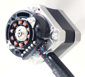
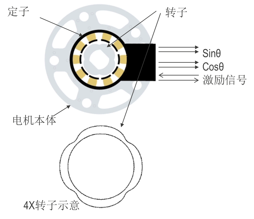
The working principle of a rotary transformer is fundamentally similar to that of a conventional transformer. The stator winding of the rotary transformer acts as the primary side of the transformer, receiving the excitation voltage. The rotor winding serves as the secondary side, obtaining induced voltage through magnetic coupling via electrical resonance.
The primary and secondary windings of the rotary transformer change their relative positions according to the angular displacement of the rotor, resulting in the output voltage amplitude of the windings being related to the rotor angle in a sine and cosine function. By performing analog-to-digital conversion on the output signal and calculating the arctangent value, the current angular displacement of the rotor can be obtained, and the derivative of angular displacement with respect to time gives the rotational speed.
Next, let’s discuss Renesas’s high-precision rotary transformer motor control scheme.
1
Rotary Transformer Motor Control Scheme
Renesas Electronics has developed a high-precision motor control solution based on rotary transformers, having independently researched and developed a new Resolver-to-Digital Converter (RDC) IC, and combined it with RX series microcontrollers (MCUs) to launch a high-precision rotary transformer motor control solution. This solution is widely applicable to motor control systems in industrial and consumer applications.
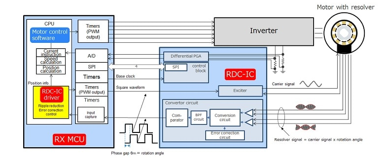
The above figure shows the block diagram of the scheme. In this scheme, the RDC IC and RX MCU process signals from the rotary transformer into angular information, while the RX MCU can also control the operation of the motor. The RX MCU provides dedicated drivers for the RDC IC, allowing easy execution of rotary transformer processing using API interfaces.
2
Main Features of Renesas RDC IC
The Renesas RDC IC has the following main features:
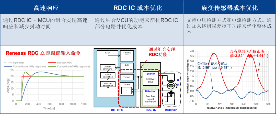
Firstly, the Renesas RDC IC adopts a new phase error detection method, deriving position information by counting the phase difference on the RX MCU. The phase difference data is generated from the excitation signal in the rotary transformer signal and the rotary angle information. Compared to traditional phase tracking detection methods, the phase error detection method can achieve higher precision and faster real-time control of motors.
Traditional phase tracking detection methods using PI control servo loops include frequency characteristics, resulting in a time delay when the motor speed changes.
Example
When using 1KHz as the main frequency characteristic, a delay of 125μs occurs.
※ The delay for 1KHz input is 45°→125μs=1ms*45°/360°
⇒ Due to the sharp change in angle, the servo tracking time delay increases for step inputs. Example: 1.5-8ms for a 180° step.
In contrast, using Renesas’s phase error detection method does not involve frequency characteristics, thus eliminating the delay time.
⇒ For step inputs caused by sudden angular changes, a rapid response can be achieved (10μs for a 20° step input).
In the configuration of the rotary transformer sensor, this scheme is compatible with both voltage detection and current detection types. The rotary transformer must be a single-phase excitation with dual-phase output type. It can utilize common voltage detection rotary transformers as well as low-cost manufactured current detection rotary transformers.
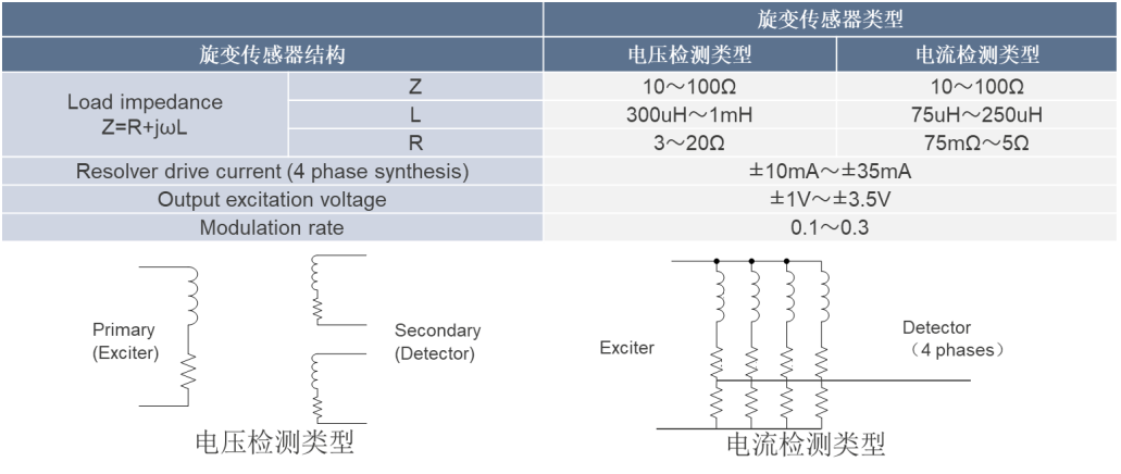
By combining with multi-pole rotary transformers, a high-resolution mechanical angle position of 200,000 P/R can be achieved, ensuring high positional accuracy. Additionally, since the RX MCU can calculate the motor’s origin position, there is no need for a Z-phase output for the motor’s origin position.
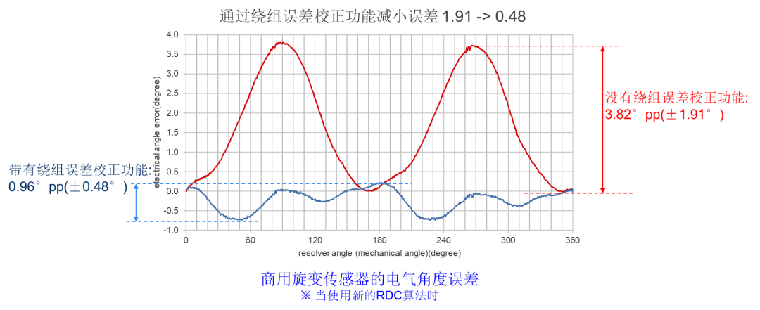
By combining the RDC IC with the RX MCU, part of the angle calculation function is offloaded to the MCU, simplifying the circuit design of the RDC IC and reducing the component cost of the RDC IC. On the other hand, by adding a unique winding error correction function, the common error of rotary transformers can be reduced from 1.91° to about 0.48°, allowing for the selection of lower-cost rotary transformers.
3
Test Data of Renesas Rotary Transformer Motor Control Scheme
Maximizing Motor Torque
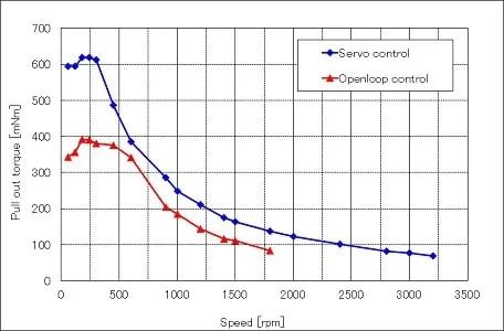
By executing servo control, the motor can achieve maximum torque and support high-speed rotation. The motor size can be reduced compared to open-loop control methods since it can be simply selected based on the required torque without considering the step loss margin.
Low Power Consumption
By using rotary transformers for servo control, standby current can be significantly reduced, consuming only the current required for the load. Additionally, current consumption can be reduced to suppress motor heating.
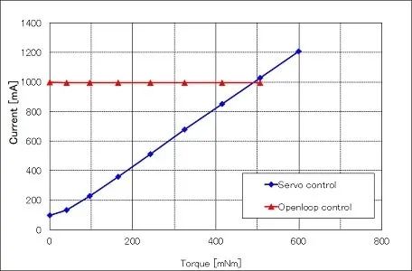
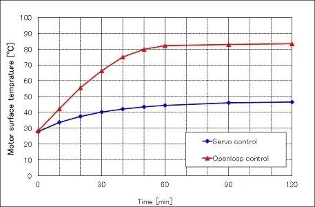
In the open-loop control process, no data was obtained as the motor lost steps when the load torque was 500mNm or greater.
Low Noise and Low Vibration
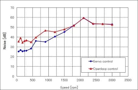
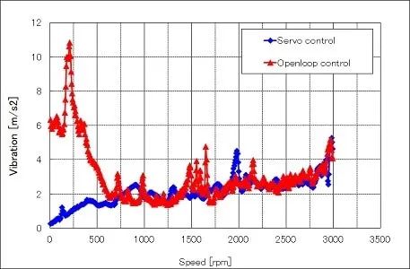
Using servo control with rotary transformers can significantly suppress noise and vibration in the mid-to-low speed range compared to open-loop control.
———— END ————

Renesas/LVGL/Qt/RT-Thread Experts Jointly Discuss: Ultra-High Performance MCU

Cortex-M85 Core Microcontroller Quick Start Guide
Process of Porting AI Models to MPU