Follow+Star Public Account Number, don’t miss out on exciting content
Author | strongerHuang
WeChat Official Account | strongerHuang
The UART is one of the most common communication methods, and it is also the most common communication interface for microcontroller debugging. It is an essential communication interface for modern microcontrollers, including the latest and most powerful Cortext-M85 core microcontroller.
Today, I will explain how to implement UART output using the Renesas Cortext-M85 core RA8 series microcontroller, which can be configured in just about a minute.
To quickly use the Renesas Cortext-M85 core RA8 series microcontroller, some preparation work is necessary.
1. Download and Install the Integrated Development Environment
There are many integrated development tools (IDE) for Renesas microcontrollers, such as Renesas’ own e2s, Keil, IAR, etc.
You can refer to my previous articles:
Renesas RA8 Series Tutorial | Setting Up the Renesas RA8 Development Environment e2s
Keil Series Tutorial: Introduction, Download, Installation, and Registration
2. Prepare the Hardware Board
Although simulation tools can perform some functions of microcontrollers, it is best to run programs on real hardware to better learn the technology.
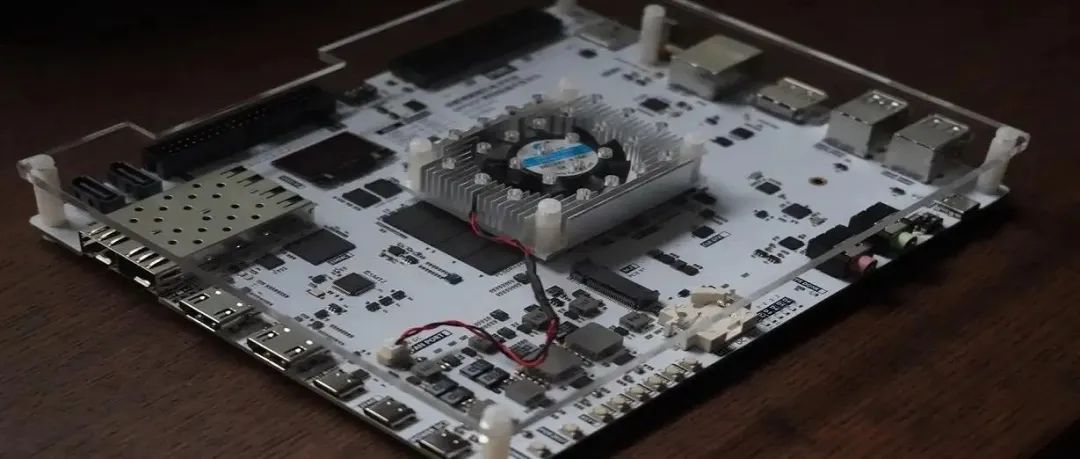
This tutorial uses the Renesas CPKCOR_RA8D1B evaluation board, which uses the RA8D1 microcontroller and integrates J-Link, allowing us to connect to a computer with just one cable for downloading and debugging.
Of course, if your board does not have an integrated J-Link, you will need to prepare one separately.
The above are the main preparations, which are actually quite simple and necessary for beginners.
Get Started with Cortext-M85 Microcontroller UART in One Minute
The e2s integrates many features, allowing us to quickly create and generate a project with just a few clicks.
1. Quickly Create a Project Based on e2s
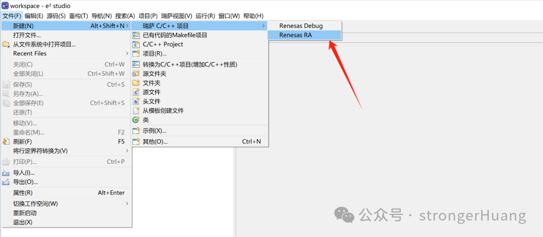
Open e2s, go to File -> New -> Renesas C/C++ Project -> Renesas RA:
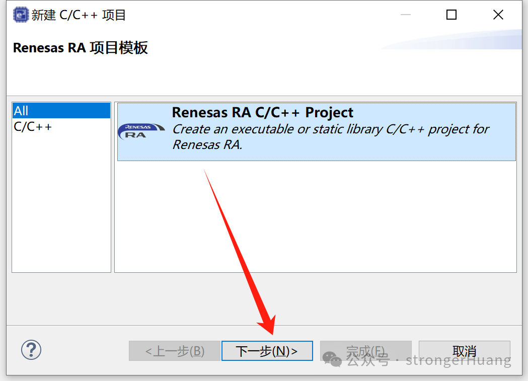
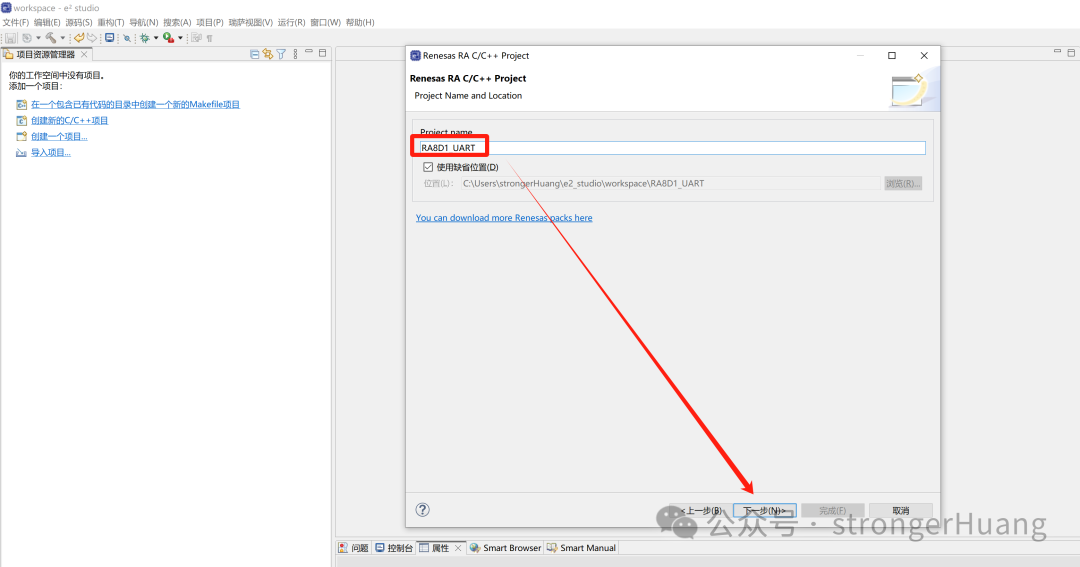
Input the project name, for example, we input RA8D1_UART:
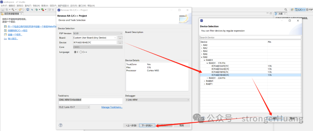
Select the microcontroller model, for example, R7FA8D1BHEC:
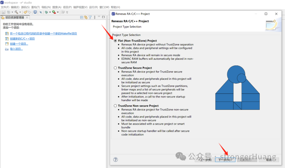
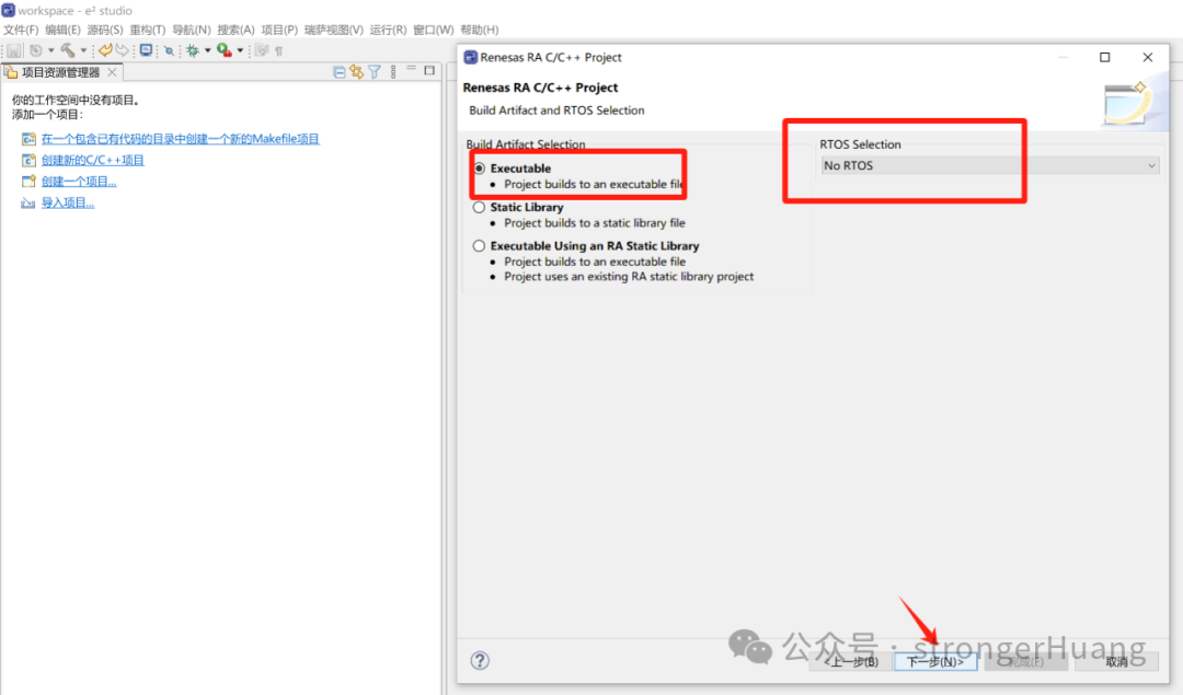
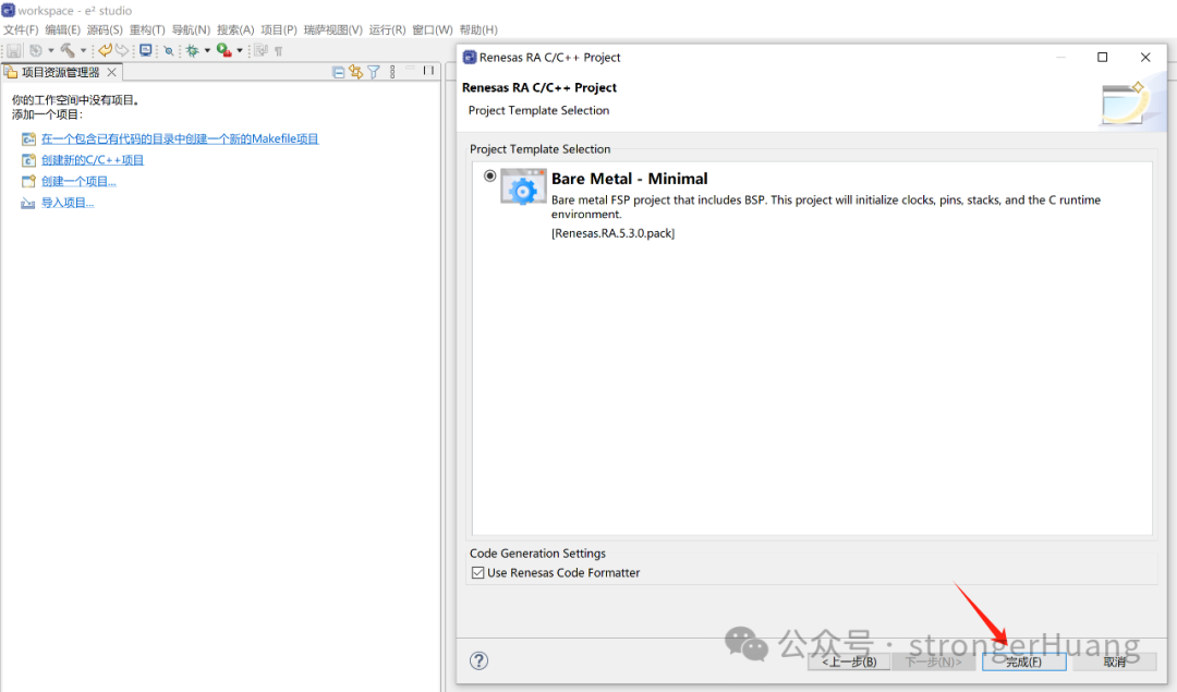
Then, follow the prompts step by step to create an RA8 project:
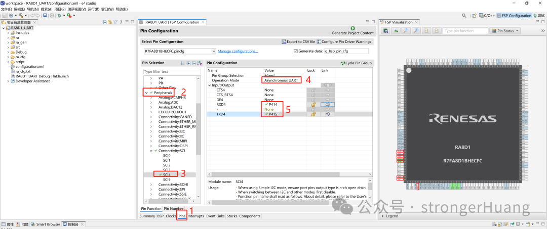
You only need to configure the UART using the graphical interface to make it operational.
In the Pins section, select Peripherals -> SLI4, and configure it to asynchronous communication mode:
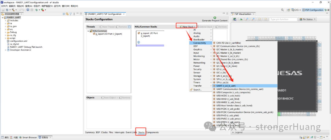
In Stacks -> New Stacks, create a UART:
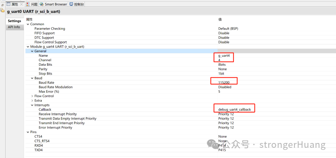
Then, configure the UART parameters (attributes):
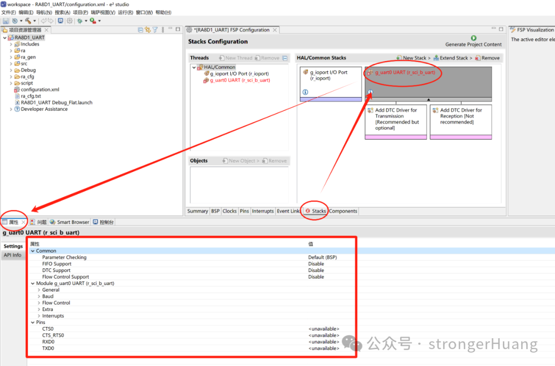
Modify a few main parameters according to your situation; most others can remain default. If you need interrupts, you will need to define an interrupt callback function:
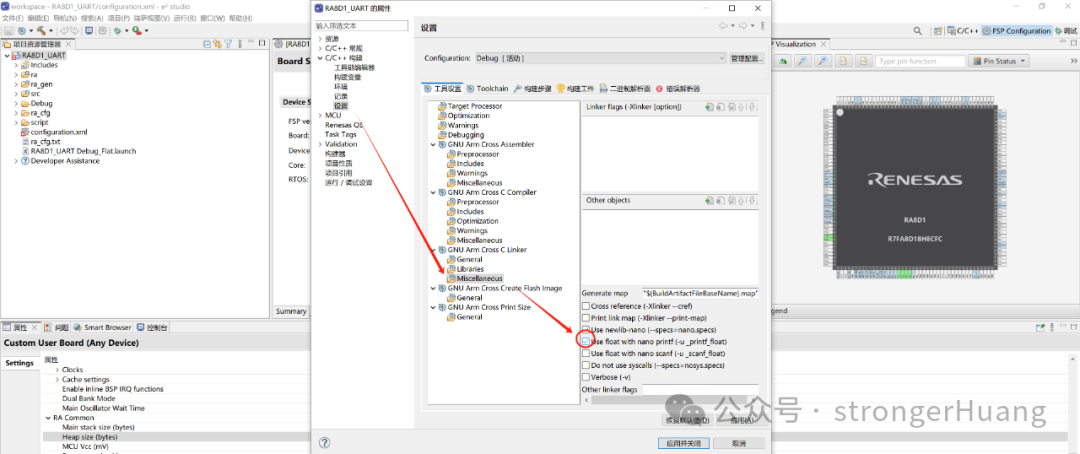
If you want to use printf, you will also need to configure two places: 1. heap stack size; 2. project settings.
Next, we will add the code. We will add two source files: bsp_debug_uart.h and bsp_debug_uart.c
Among them, bsp_debug_uart.h includes header files and declares functions.
#ifndef __BSP_DEBUG_UART_H#define  __BSP_DEBUG_UART_H#include "hal_data.h"#include <stdio.h>
void Debug_UART4_Init(void);
#endif
And the bsp_debug_uart.c source file is also quite simple:
#include "bsp_debug_uart.h"
/* Debug UART4 Initialization */
void Debug_UART4_Init(void){    fsp_err_t err = FSP_SUCCESS;        err = R_SCI_B_UART_Open(&g_uart4_ctrl, &g_uart4_cfg);
    assert(FSP_SUCCESS == err);}
/* Send Complete Flag */
volatile bool uart_send_complete_flag = false;
/* UART Interrupt Callback */
void debug_uart4_callback (uart_callback_args_t * p_args){    switch (p_args->event)    {        case UART_EVENT_RX_CHAR:        {            /* Echo back the received data */            R_SCI_B_UART_Write(&g_uart4_ctrl, (uint8_t *)&(p_args->data), 1);
            break;        }        case UART_EVENT_TX_COMPLETE:        {            uart_send_complete_flag = true;            break;        }        default:            break;    }}
/* Redirect printf output */
#if defined __GNUC__ && !defined __clang__int _write(int fd, char *pBuffer, int size); // Prevent compile warning
int _write(int fd, char *pBuffer, int size){    (void)fd;    R_SCI_B_UART_Write(&g_uart4_ctrl, (uint8_t *)pBuffer, (uint32_t)size);
    while(uart_send_complete_flag == false);    uart_send_complete_flag = false;
    return size;}#elseint fputc(int ch, FILE *f){    (void)f;    R_SCI_B_UART_Write(&g_uart4_ctrl, (uint8_t *)&ch, 1);
    while(uart_send_complete_flag == false);    uart_send_complete_flag = false;
    return ch;}
#endif
That’s it! Now, whatever character you send to the microcontroller, it will echo back, for example: if you send the character “A”.
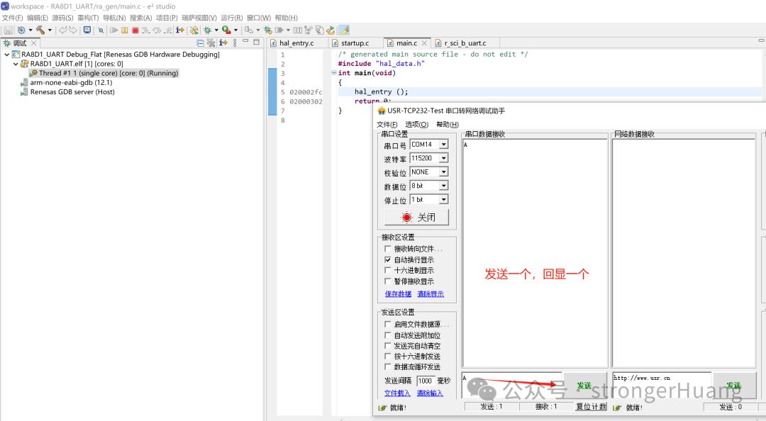
Now you have completed the UART configuration for the RA8 microcontroller. Isn’t it simple? For those with some foundation, it can basically be done in one minute.
Using the OpenAMP Framework for Inter-Core Communication and Applications in Multi-Core Processors
Sharing a Lightweight Open Source Face Recognition Algorithm
The Differences Between Release and Debug in Microcontroller Development Environments