Beginners in Mitsubishi PLC should master the fundamental logic instructions and common function instructions, focusing on understanding the logical significance of the instructions and their practical application scenarios. The following are the core essential instructions:
1. Fundamental Logic Instructions (Building Simple Control Circuits)
This is the “syntax foundation” of PLC programming, corresponding to the normally open, normally closed, and coil controls of relays, which are the core of all programs.
• LD/LDI/LDP/LDF: Load Instructions (Load Contacts)
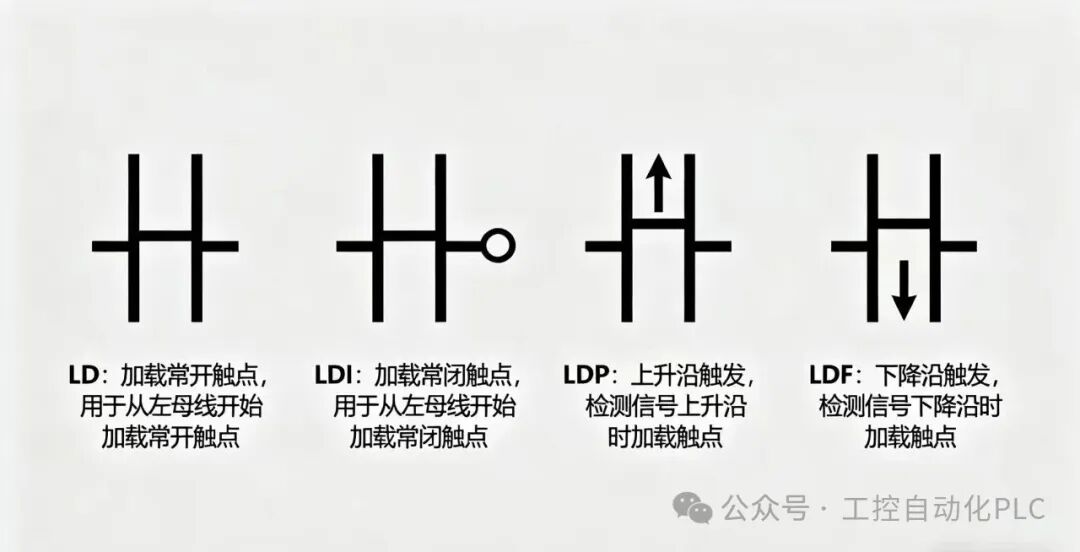
◦ LD: Load normally open contact; LDI: Load normally closed contact;
◦ LDP: Rising edge trigger (executes once when the contact changes from OFF to ON); LDF: Falling edge trigger (executes once when the contact changes from ON to OFF).
• AND/ANI/ANDP/ANDF: AND Instructions (Series Contacts)
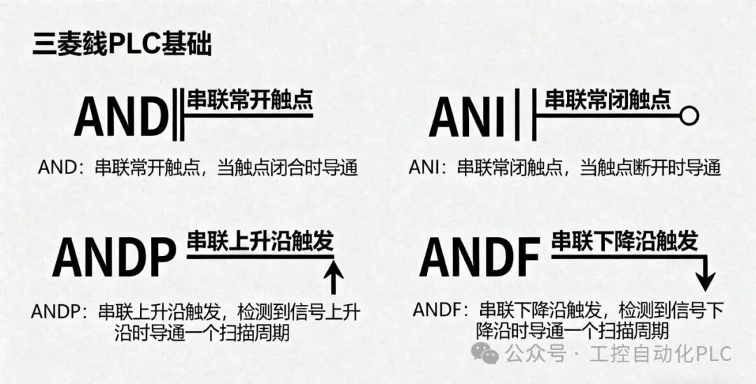
◦ AND: Series normally open contacts; ANI: Series normally closed contacts;
◦ ANDP/ANDF: Series rising edge/falling edge trigger contacts.
• OR/ORI/ORP/ORF: OR Instructions (Parallel Contacts)
◦ OR: Parallel normally open contacts; ORI: Parallel normally closed contacts;
◦ ORP/ORF: Parallel rising edge/falling edge trigger contacts.
• OUT: Coil output instruction (controls the energization of relays, timers, counters, etc.).
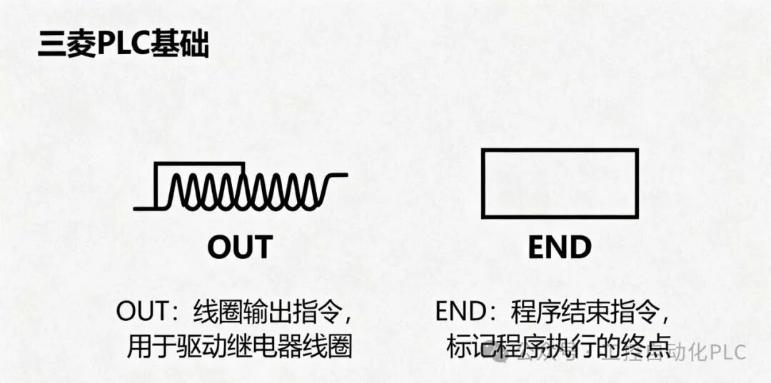
• END: Program end instruction (the program stops executing at this point and returns to the beginning to loop).
2. Common Function Instructions (Achieving Core Control Needs)
Mastering these instructions can accomplish practical functions such as “delay, counting, data processing,” which are key from “entry” to “application”.
1. Timer Instructions (T): Implementing Delay Control
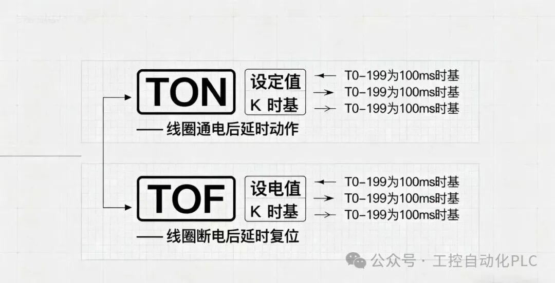
◦ TON (On Delay): After the coil is energized, it delays to the set value, and the contact acts (e.g., “the light turns on after pressing the button for 3 seconds”).
◦ TOF (Off Delay): After the coil is de-energized, it delays to the set value, and the contact resets (e.g., “the light turns off after releasing the button for 3 seconds”).
◦ Note: In Mitsubishi PLC, timer numbers correspond to different time bases (e.g., T0-T199 for 100ms time base, a set value of 10 represents 1 second).
2. Counter Instructions (C): Implementing Count Statistics
◦ CTU (Count Up): Each time the rising edge of the count input is detected, the count value increases by 1, and the contact acts when it reaches the set value (e.g., “an alarm after the product passes the conveyor belt 5 times”).
◦ CTD (Count Down): Each time the rising edge of the count input is detected, the count value decreases by 1, and the contact acts when it reaches 0.
3. Set/Reset Instructions (SET/RST): Locking State
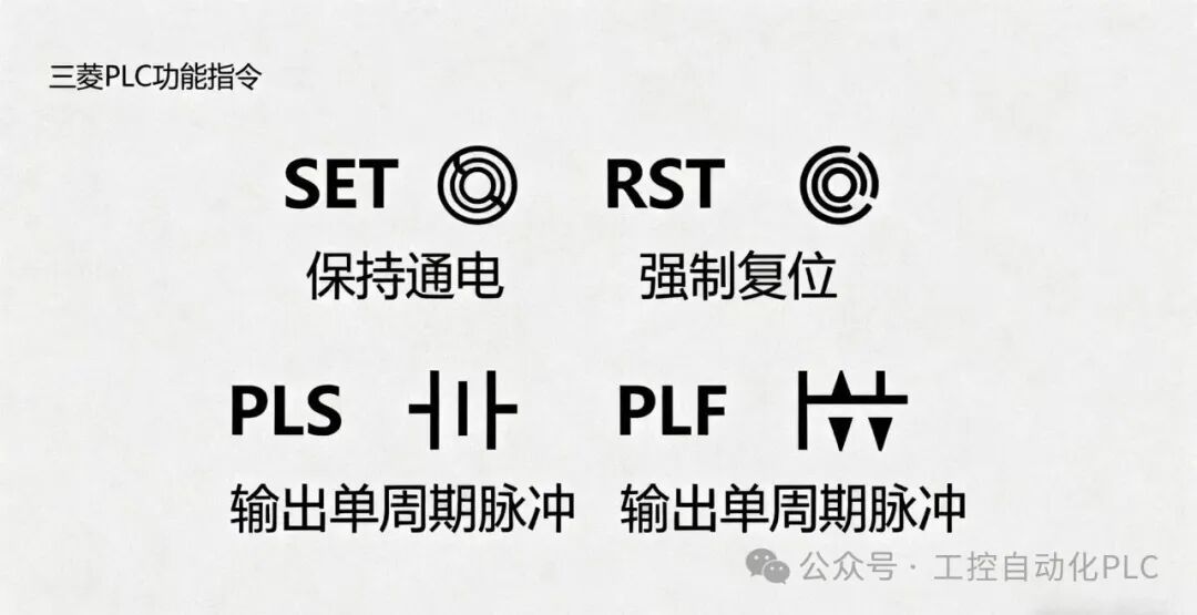
◦ SET: Keeps the coil energized (sets to 1), and it does not reset even if the trigger signal disappears;
◦ RST: Resets the coil to de-energized (sets to 0), which needs to be triggered separately (e.g., “press the start button to SET the light on, press the stop button to RST the light off”).
4. Pulse Instructions (PLS/PLF): Generating a Single Pulse
◦ PLS: Outputs a pulse for one scan cycle when the coil is energized;
◦ PLF: Outputs a pulse for one scan cycle when the coil is de-energized (commonly used to trigger counters and data registers).
5. Data Transfer Instructions (MOV): Data Assignment
◦ Transfers source data (e.g., constant K100) to the target register (e.g., D0), which is the basis for data processing (e.g., “transfer the set delay time of 100 to D0 for the timer to call”).
3. Key Principles for Beginners
1. First practice “Fundamental Logic Instructions”: use LD/AND/OR/OUT to build the “Start-Stop Circuit” (the most classic entry case) to understand the “scan execution” logic of PLC.
2. Then learn “Function Instructions”: practice timers and counters in conjunction with practical scenarios (e.g., “delay light on” and “count alarm”).