
Those involved in industrial automation know that whether the PLC can communicate with the host computer directly determines whether the entire system can operate. Omron’s Fins/TCP and HostLink protocols are the most commonly used on-site, but beginners often stumble on handshake and address configuration. This article does not delve into theoretical concepts; instead, it follows the on-site debugging process step by step, from wiring to troubleshooting, so you can directly apply what you learn.
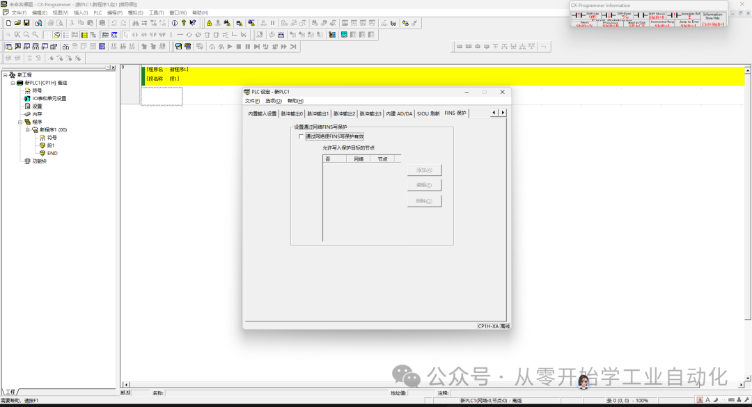
1. Fins/TCP Protocol: Practical Ethernet Communication
Fins/TCP is currently mainstream, operating over Ethernet with fast speeds (10~100MB/s), and can connect up to 254 nodes. Just pull a network cable on-site, and it’s much cleaner than serial communication. However, there is a pitfall:The node address must match the last digit of the IP address, which many people overlook during their first configuration.
Step 1: Establish Communication Handshake (The Most Commonly Overlooked Step On-Site)
Fins/TCP does not work just by plugging in the network cable; a handshake must be established first—equivalent to “introducing each other”—otherwise, the PLC will not recognize the commands you send.
1. Client Sends Handshake Request (Computer → PLC)
You need to send a 20-byte command frame. Here’s the format you can use by just changing the node address:
46494E53 0000000C 00000000 00000000 00000005- The first 4 bytes “46494E53” are fixed, representing the ASCII code for “FINS”; changing this will result in an error;
- 0000000C is the frame length (12 hex = 20 bytes), do not change;
- The last group “00000005” is your computer’s node address—it must match the last digit of your computer’s IP! For example, if your computer’s IP is 192.168.1.5, you should fill in 05 here.
2. PLC Responds (PLC → Computer)
If the handshake is successful, the PLC will return a 24-byte frame:
46494E53 00000010 00000001 00000000 00000005 00000020- The response code “00000001” means “success”;
- The last group “00000020” is the PLC’s node address (32 decimal), make a note of it! You will need it for sending commands later.
Common Pitfall On-Site: Never resend the handshake command! I have seen people unable to connect, repeatedly clicking send, resulting in the PLC returning error 00000003 (unsupported command) and even closing the port, requiring a PLC restart to recover.
Step 2: Error Code Troubleshooting (Quick Reference for On-Site Debugging)
If the handshake fails, don’t panic; check the error code returned by the PLC and make the corresponding adjustments below, which is much faster than trial and error.
Here’s a small tip: If you can’t connect, check three things: ① Are the computer and PLC on the same subnet (e.g., both are 192.168.1.X)? ② Is the firewall turned off (especially in Windows 10/11, which can block port 9600)? ③ Are the node address and the last digit of the IP correct (this is mandatory, no exceptions).
Step 3: FINS Frame Read/Write Data (Using Practical Examples)
Once the handshake is successful, you can send commands to read and write data. The FINS frame format is “header + length + command + content”, with a length of 12~2012 bytes. Commonly used on-site are reading DM areas, writing W areas, and forcing bits. I will provide one practical example for each; just modify the addresses accordingly.
Example 1: Read DM0, DM1 (Commonly Used for Parameter Checking On-Site)
Send Command Frame (Read 2 channels):
46494E53 0000001A 00000002 00000000 80000200 20000005 00FF0101 82000000 0002- 20000005: The previously noted PLC node 20, computer node 05 (do not confuse them!);
- 00FF0101: 0101 is the operation code for “read”, fixed;
- 82000000: 82 represents the DM area, 0000 is the starting address (DM0);
- 0002: Read 2 (DM0 and DM1).
PLC Response Frame (If successful):
46494E53 0000001A 00000002 00000000 C0000200 05000020 00FF0101 00001234 5678- The last values 1234 and 5678 are the values of DM0 and DM1, respectively; just note them down.
Example 2: Write W210=0388 (Commonly Used for Setting Parameters)
Send Command Frame:
46494E53 0000001C 00000002 00000000 80000200 20000005 00FF0102 B100D200 00010388- 00FF0102: 0102 is the operation code for “write”;
- B100D200: B1 is the W area code, 00D2 is the address (hex00D2=210, which is W210);
- 00010388: Write 1 data point, value is 0388.
PLC Response Frame (If successful, it returns this):
46494E53 00000016 00000002 00000000 C0000200 05000020 00FF0102 0000- The last part is 0000, which means “written successfully”, no issues.
Example 3: Force W212.01=On (Temporary Control Point for On-Site Debugging)
Sometimes you need to temporarily turn on a point for testing, use force:
Send Command Frame:
46494E53 0000001C 00000002 00000000 80000200 20000005 00FF2301 00010001 3100D401- 00FF2301: 2301 is the operation code for “force”;
- 00010001: 1 point, 0001 is “set” (On);
- 3100D401: 31 is the W bit code, 00D401 is the address (hex00D4=212, 01 is the bit, which is W212.01).
Check Result : Open CX-Programmer, and if W212.01 shows “(forced)” next to it, it means it worked. Remember to cancel the force after testing (just change 0001 to FFFF).
2. HostLink Protocol: The Old Method of Serial Communication
HostLink is an old protocol, operating over RS-232C or RS-422, with a 1-to-1 distance of up to 15 meters and a 1-to-many distance of up to 500 meters, connecting a maximum of 32 PLCs. It is rarely used in new projects, but it is still necessary for retrofitting old equipment. Its commands start with @ in ASCII code; just remember a few common ones.
Common Commands: Write W Area, Read W Area, Force Bit
1. Write W210=0388 (PLC Address 0)
Send Command:
@00FA0000000000102B100D2000001038873*CR- @00: PLC address 0 (when there are multiple PLCs on-site, the address starts from 0);
- B1: W area code;
- 00D200: Address of W210 (hex00D2=210);
- 0388: The value to be written;
- 73: Checksum (no need to calculate yourself, serial port tools can generate it automatically).
PLC Response:
@00FA00400000000102000040*CR- The middle part has 0000, indicating a successful write.
2. Force W212.01=On
Send Command:
@00FA0000000002301000100013100D40104*CR- 00010001: 1 point, 0001 is set;
- 31: W bit code;
- 00D401: Address of W212.01.
On-Site Reminder: When using RS-422 with HostLink,120Ω termination resistors must be connected at both ends of the bus, otherwise, packets may be lost over long distances. I previously had a 300-meter line in the workshop that kept disconnecting without resistors, but it worked fine once they were connected.
3. Common Network Configuration Issues
Network Configuration: How to Set the Ethernet Option Board?
No matter which protocol is used, the PLC’s IP must be set correctly first. The default IP of Omron’s Ethernet option board (e.g., CIF41) is 192.168.250.1, and changing the IP on-site is very simple; it can be done using a browser:
1. Steps to Change PLC IP (On-Site Practice)
(1) Connect the computer to the PLC’s network port and change the computer’s IP to 192.168.250.X (X≠1); (2) Open a browser and enter http://192.168.250.1/C00.htm, the password is “ETHERNET” (all uppercase, do not mistype);(3) Go to “System Settings” and change the IP (e.g., 192.168.1.32), subnet mask 255.255.255.0;(4) A key step: Set the FINS node address to the last digit of the IP (32), otherwise, the handshake will definitely fail;(5) Click “Transfer” to save, then click “Restart”, and wait a moment for it to take effect.
2. Forgot PLC IP? Here’s How to Check!
It is common to encounter situations where the PLC IP is unknown on-site; don’t panic, just check the PLC’s registers:
- Model CP1H/L/E-30/40/60:
- Option board in slot 1: IP is stored in D32155-D32156;
- In slot 2: IP is stored in D32455-D32456;
- Model CP1H/L/E-14/20: There is only 1 slot, IP is in D32455-D32456.
Example: Check D32455=16#C0A8, D32456=16#0120;
- C0A8 converted to decimal is 192.168, 0120 is 1.32, so the IP is 192.168.1.32; just use this to connect.
4. Finally: How to Choose a Protocol? Suggestions for On-Site
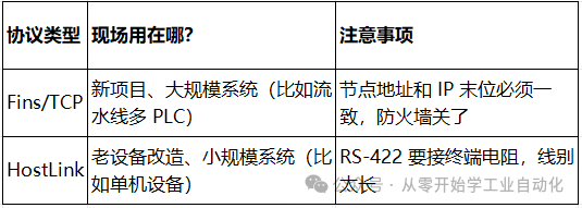
Experience from Someone Who’s Been There:
- For new projects, prioritize using Fins/TCP; it’s easier to add devices later without rewiring;
- For critical devices, consider implementing “protocol redundancy”—for example, primary Fins/TCP and backup HostLink, so if one fails, the other can still be used;
- No matter which protocol is used, always record the communication parameters (IP, node address, port) on the device label; otherwise, it will be hard to find during maintenance next time.
5. C# Winforms Code I will provide it in the link to the next article; it would take up too much space here, so please stay tuned.
This process has been used countless times on-site, covering everything from wiring to troubleshooting. When you configure for the first time, I recommend testing the connection with the PLC in the office before taking it on-site to connect to the equipment; this can save you a lot of detours. If you encounter strange errors, feel free to ask me in the comments, and we can figure it out together!
If you find this useful, please help by following and saving it.
Sharing on how to achieve D and M sharing with multiple Mitsubishi FX3U PLCs (practical sharing)
Beginner project [Automatic Screw Machine] C#, PLC, Touch Screen Practical (2/5): C# Winforms Host Computer Design
Assistant Electrical Engineers Can Also Start C# Host Computer Programming: Mitsubishi FX3U PLC Serial Communication Winforms Interface Development (with actual source code)