Editor’s Note: This article is primarily compiled from Keysight’s related content on probes.
Oscilloscopes have expanded their application range due to the existence of probes, enabling online testing and analysis of the electronic circuits being measured, as shown in the figure below:
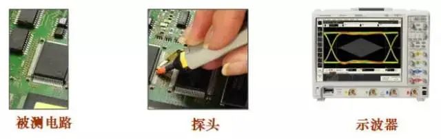
Function of Oscilloscope Probes
The selection and use of probes need to consider the following two aspects:
Firstly: Because probes have loading effects, they will directly affect the measured signals and circuits;
Secondly: Probes are part of the entire oscilloscope measurement system, which will directly affect the instrument’s signal fidelity and test results.
Loading Effects of Probes
Once the probe detects the measured circuit, it becomes part of the measured circuit. The loading effect of the probe includes the following three components:
-
Resistive loading effect;
-
Capacitive loading effect;
-
Inductive loading effect.
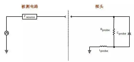
Loading Effects of Probes
The resistive load is equivalent to paralleling a resistor on the measured circuit, which has a voltage divider effect on the measured signal, affecting the amplitude and DC offset of the measured signal. Sometimes, when adding the probe, a faulty circuit may appear to be normal. It is generally recommended that the probe resistance R > 10 times the source resistance to maintain an amplitude error of less than 10%.

Resistive Load of Probes
The capacitive load is equivalent to paralleling a capacitor on the measured circuit, which filters the measured signal, affecting the rise and fall times of the measured signal, affecting transmission delay, and influencing the bandwidth of the transmission interconnect channel. Sometimes, when adding the probe, a faulty circuit becomes normal, and this capacitive effect plays a critical role. It is generally recommended to use probes with as small a capacitive load as possible to reduce the impact on the edges of the measured signal.
Capacitive Load of Probes
The inductive load comes from the inductive effect of the probe’s ground wire, which can resonate with the capacitive and resistive loads, causing ringing in the displayed signal. If ringing appears significantly on the displayed signal, it is necessary to check whether it is a real feature of the measured signal or caused by the ground wire. The method to confirm this is to use the shortest ground wire possible. It is generally recommended to use the shortest ground wire; the typical ground wire inductance = 1nH/mm.
Inductive Load of Probes
Oscilloscope probes can be broadly divided into two categories: passive probes and active probes. Passive and active refer to whether the probe needs to be powered.
Passive probes are further divided as follows:
-
Low-resistance voltage divider probes;
-
High-impedance passive probes with compensation (the most commonly used passive probes);
-
High-voltage probes
Active probes are further divided as follows:
-
Single-ended active probes;
-
Differential probes;
-
Current probes
The most commonly used high-impedance passive probes and active probes are compared simply below:
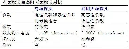
Comparison of Active and Passive Probes
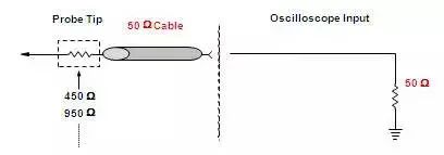
Low-resistance voltage divider probes have lower capacitive load (<1pf), higher bandwidth (>1.5GHz), and lower price, but the resistive load is very large, generally only 500ohm or 1Kohm, so they are only suitable for testing circuits with low source impedance or circuits focused on time parameter testing.

Structure of Low-input-resistance Probes
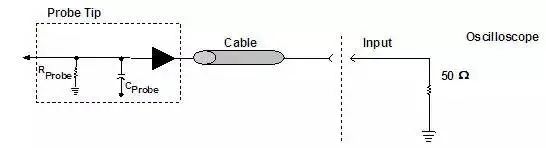
High-impedance passive probes with compensation are the most commonly used passive probes, and generally, the probes that come standard with oscilloscopes are of this type. High-impedance passive probes with compensation have high input resistance (generally above 1Mohm), adjustable compensation capacitance to match the oscilloscope’s input, and a high dynamic range to test larger amplitude signals (tens of volts and above) at a low price. However, the downside is that the input capacitance is too large (generally over 10pf) and the bandwidth is lower (generally within 500MHz).
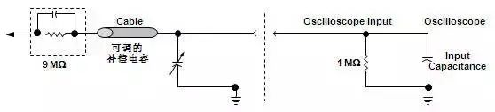
Structure of Common Passive Probes
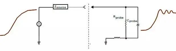
High-impedance passive probes with compensation have a compensation capacitor, and when connected to the oscilloscope, it generally requires adjusting the capacitance value (using the small screwdriver provided with the probe to adjust, connecting the probe to the oscilloscope’s compensation output test position) to match the oscilloscope’s input capacitance to eliminate low-frequency or high-frequency gain. The left side of the figure shows the presence of high-frequency or low-frequency gain, while the adjusted compensation signal displays the waveform as shown on the right.
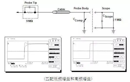
Compensation of Passive Probes
High-voltage probes are based on high-impedance passive probes with compensation but increase the input resistance, resulting in greater attenuation (e.g., 100:1 or 1000:1, etc.). Because high-voltage components are required, high-voltage probes are generally larger in physical size.
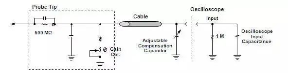
Structure of High-voltage Probes
First, let’s observe the effect of using a 600MHz passive probe and a 1.5GHz active probe to test a 1ns rise time step signal.Using a pulse generator to produce a 1ns step signal, after testing fixtures, it is directly connected to a 1.5GHz bandwidth oscilloscope via SMA cable, so the oscilloscope will display a waveform (the blue signal in the figure below), storing this waveform as a reference waveform.Then, using the probe to measure the testing fixture to detect the measured signal, the waveform from the SMA direct connection becomes the yellow waveform due to the loading effect of the probe, while the waveform displayed on the probe channel is the green waveform.Then test the rise times separately, and it can be seen how passive and active probes affect high-speed signals.
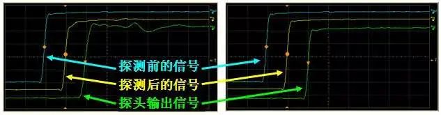
Effects of Passive and Active Probes on Measured Signals and Measurement Results
Specific test results are as follows:
Using the 1165A 600MHz passive probe with crocodile ground wire: affected by the probe load, the rise time becomes: 1.9ns; the waveform displayed on the probe channel has ringing, and the rise time is: 1.85ns;
Using the 1156A 1.5GHz active probe with a 5cm ground wire: the effect of probe load is minimal, and the rise time remains: 1ns; the waveform displayed on the probe channel is consistent with the original signal, and the rise time remains: 1ns.
The structure diagram of the single-ended active probe is shown below, using an amplifier to achieve impedance transformation. The input impedance of the single-ended active probe is relatively high (generally over 100Kohm), while the input capacitance is relatively small (generally less than 1pf), connected to the oscilloscope through the probe amplifier, and the oscilloscope must use a 50ohm input impedance.
Active probes have broad bandwidth (now up to 30GHz) and small load, but they are relatively expensive (generally about 10% of the oscilloscope price for the same bandwidth), with a smaller dynamic range (this needs attention, as signals exceeding the probe’s dynamic range cannot be tested correctly. Generally, the dynamic range is about 5V), and they are relatively fragile, requiring careful use.
Structure of Active Probes
The structure diagram of the differential probe is shown below, using a differential amplifier to achieve impedance transformation. The input impedance of the differential probe is relatively high (generally over 50Kohm), while the input capacitance is relatively small (generally less than 1pf), connected to the oscilloscope through the differential probe amplifier, and the oscilloscope must use a 50ohm input impedance.
Differential probes have very wide bandwidth (now up to 30GHz), very small load, and a high common mode rejection ratio, but they are relatively expensive (generally about 10% of the oscilloscope price for the same bandwidth), with a smaller dynamic range (this needs attention, as signals exceeding the probe’s dynamic range cannot be tested correctly. Generally, the dynamic range is about 3V), and they are relatively fragile, requiring careful use.
Differential probes are suitable for testing high-speed differential signals (no grounding required during testing), suitable for amplifier testing, power supply testing, and virtual ground testing applications.
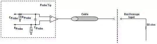
Structure of Differential Probes
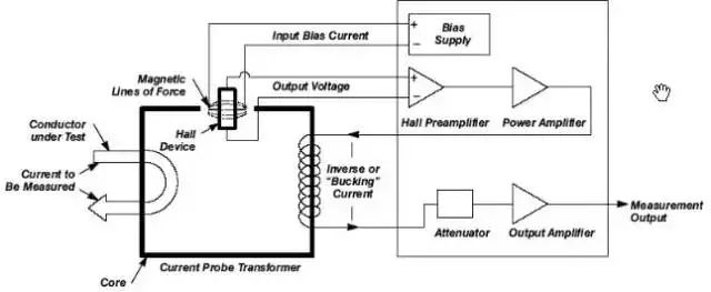
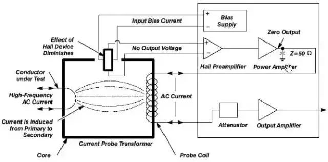
Current probes are also active probes that utilize Hall sensors and inductive coils to measure DC and AC currents. Current probes convert current signals into voltage signals, which the oscilloscope captures and displays as current signals. Current probes can test currents from tens of milliamps to hundreds of amps, and during use, the current line needs to be passed out (current probes test by clamping the wire in the middle, which does not affect the measured circuit).
Working Principle of Current Probes When Testing DC and Low-frequency AC:
When the current clamp is closed, enclosing a conductor carrying current, a magnetic field will be generated accordingly.These magnetic fields cause the electrons within the Hall sensor to deflect, generating an electromotive force at the output of the Hall sensor.The current probe generates a reverse (compensating) current sent to the coil of the current probe based on this electromotive force, making the magnetic field within the current clamp zero to prevent saturation.The current probe measures the actual current value based on the reverse current.Using this method, it is possible to measure large currents very linearly, including mixed AC and DC currents.
Working Principle of Current Probes When Testing DC and Low-frequency
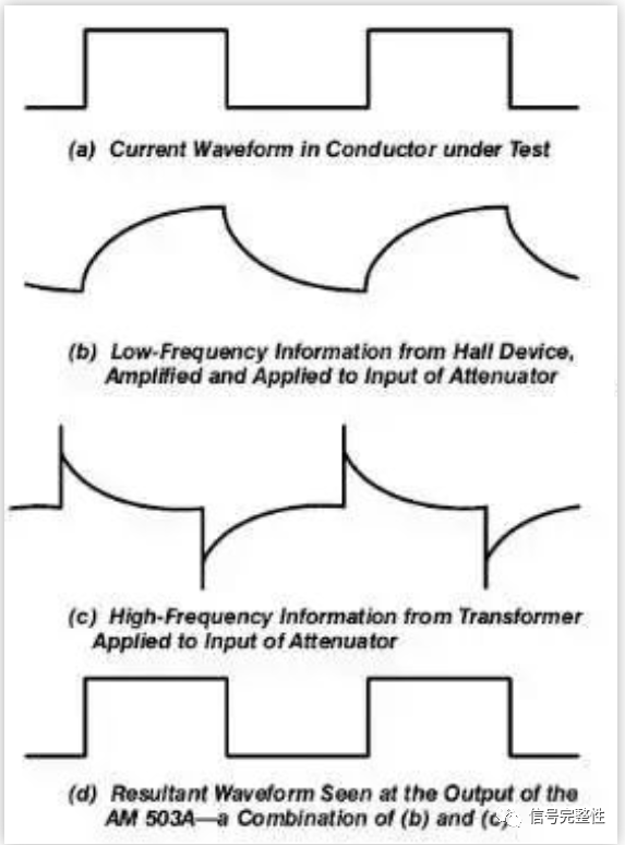
Working Principle of Current Probes When Testing High-frequency:
As the frequency of the measured current increases, the Hall effect gradually weakens. When measuring a high-frequency AC current that does not contain a DC component, most of it is sensed directly through the strength of the magnetic field into the coil of the current probe. At this point, the probe acts like a current transformer, and the current probe directly measures the induced current rather than the compensating current, with the amplifier’s output providing a low-impedance ground loop for the coil.
Working Principle of Current Probes When Testing High-frequency
Working Principle of Current Probes in the Cross-over Region:
When the current probe operates in the high-low frequency crossover region at 20KHz, part of the measurement is achieved through the Hall sensor, while another part is achieved through the coil.
Working Principle of Current Probes in the Cross-over Region
Accuracy Verification of Probes and Accessories
The following is an example: the measured signal is a clock signal with a frequency of 456MHz and a rise time of about 65ps, tested using different types of probes and probe accessories.
-
Figure A is the test result using the 12GHz 1169A differential probe and the N5381A 12GHz soldering probe accessory, which almost completely reproduces the measured signal;
-
Figure B is the test result using a 500MHz passive probe, which completely distorts the displayed signal;
-
Figure C is the test result using the 12GHz 1169A differential probe with longer test leads, which shows significant overshoot in the displayed signal;
-
Figure D is the test result using the 4GHz 1158A single-ended probe with longer test leads, which shows the displayed signal is nearly a sine wave, with significant distortion.
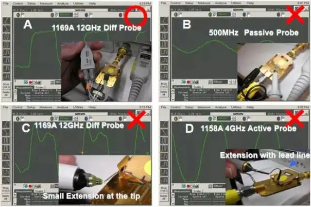
Comparison of Testing Results with Different Probe Accessories
As can be seen from the figure, the impact of probes and probe accessories on testing accuracy is significant, which is one of the key points we should pay attention to when testing high-speed signals. How should we verify the probes and probe accessories?
Verifying probes and probe accessories requires using a pulse code generator (e.g., 81134A, with a rate of 3.35GHz and a rise time of 60ps). If the oscilloscope has a built-in high-speed signal output function, the auxiliary output of the oscilloscope can also be used to replace the pulse code generator (for example, the AUX OUT port of the Infiniium oscilloscope can output a high-speed clock: 456MHz frequency, with a rise time of about 65ps).
Additionally, coaxial cables and testing fixtures are needed (the probe calibration fixture configured with the Infiniium oscilloscope can serve as the verification test fixture for probes and probe accessories). The outer surface of the test fixture is ground, and the internal wiring is for signal, as shown in the figure below. During use, one end is connected to the pulse code generator or the oscilloscope’s auxiliary output AUX OUT port via a coaxial cable, and the other end is connected to channel 1 of the oscilloscope via an adapter.
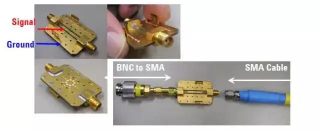
Probe Verification Fixture
Then connect the probe to be verified to channel 2, allowing the probe to contact the signal and ground of the test fixture (if it is a differential probe, connect the + terminal to the signal line of the test fixture and the – terminal to the ground of the test fixture).
-
If the probe does not contact the signal line, a raw waveform will appear on the screen, stored as a reference waveform;
-
When the probe detects the signal line, the waveform on channel 1 will change, and this changed waveform is the measured signal affected by the probe and probe accessories;
-
At this point, the waveform on channel 2 connected to the probe will appear, which is the waveform detected by the probe;
-
By comparing the reference waveform, the waveform on channel 1, and the waveform on channel 2 connected to the probe, the differences among the three can be visually observed or read out through test parameters, allowing verification of the effects of the probe and probe accessories.
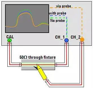
Probe Verification Connection and Principle
The following is an example of actual verification. Figure A connects the oscilloscope’s AUX OUT to the test fixture via a coaxial cable, and the other end of the test fixture connects to a channel of the oscilloscope through an SMA-PBNC adapter (in this example, connected to channel 3). Connect the probe to channel 1, adjusting the waveform on the screen to produce a rising edge waveform, as shown in Figure C, and store this waveform as a reference waveform.In Figure B, the probe and accessory to be verified are point-measured on the test fixture, as shown in Figure D. The screen displays three waveforms: the blue is the reference waveform, the green is the measured waveform affected by the probe, and the yellow is the waveform displayed by the probe. By testing the rise time parameters, overshoot parameters, etc., the performance of the probe and probe accessories can be confirmed.
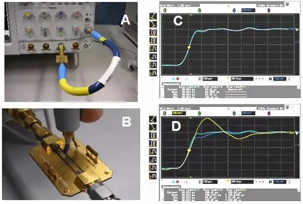
Probe Verification Example
Friends who need to learn ADS simulation can scan the QR code below (or read the original text) to purchase “ADS Signal Integrity Simulation and Practice”.
Hardened website book purchase, with additional fan benefits as follows:
Click to read the original text for more details.