Editor’s Note: Oscilloscopes are almost an essential tool for electronic engineers, but not every engineer can use them effectively. This article shares seven common mistakes encountered when using oscilloscopes. These may align with what you’ve seen or differ, but of course, this is subjective.
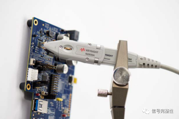
Ideally, all probes should be a wire that does not interfere with the device under test, with infinite input resistance and zero capacitance and inductance when connected to your circuit. This would precisely replicate the measured signal. However, the reality is that probes introduce loading effects on the circuit. The resistance, capacitance, and inductance components on the probe can alter the response of the circuit being measured.
Every circuit is different and has its own electrical characteristics. Thus, when probing a device, it is essential to consider the characteristics of the probe and select one that has the least impact on the measurement. Consideration includes the complete connection from the oscilloscope input through the cable to the specific connection point on the device under test, as well as any accessories or additional wires and solder used to connect to the test point.
Understanding the potential errors encountered during testing and how to improve measurements through better operation is crucial. The electrical characteristics of the probe can affect measurement results and the operation of the circuit. Taking steps to ensure these effects are within acceptable limits is a key step to successful measurements. The seven common mistakes when using oscilloscopes are as follows:
Error 1: Not Calibrating the Probe
Probes are calibrated after leaving the factory, but they are not calibrated for the oscilloscope front end. If they are not calibrated at the oscilloscope input, correct measurement results cannot be obtained.
Active Probes
If active probes are not calibrated for the oscilloscope, differences will be seen in the vertical voltage measurement results and the timing of the rising edge (along with possible distortion). Most oscilloscopes have a reference or auxiliary output function, accompanied by an operating guide to help engineers through the probe calibration process.
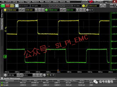
Figure 1: Generator Output and Detected Signal
Figure 1 shows a 50 MHz signal input to the oscilloscope via an SMA cable and adapter on Channel 1 (yellow trace). The green trace is the same signal input to the oscilloscope via an active probe on Channel 2. Note that the generator output on Channel 1 is 1.04 Vpp (volts peak-to-peak), while the signal detected on Channel 2 is 965 mV (millivolts). Additionally, the offset between Channel 1 and Channel 2 can be as much as 3 ms (milliseconds), causing the rise times to be misaligned.
Passive Probes
The variable capacitance of the probe can be adjusted to perfectly match the compensation with the oscilloscope input being used. Most oscilloscopes have a square wave output that can be used for calibration or reference. Probe this connection and check if the waveform is square. Adjust the variable capacitance as needed to eliminate any undershoot or overshoot.
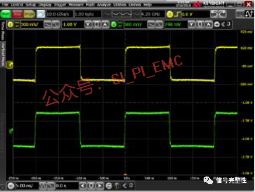
Figure 2: After Amplitude and Offset Calibration
If this probe is calibrated, the results will improve significantly. Figure 2 shows the results after appropriate amplitude and offset calibration. The amplitude is now improved to 972 mVpp, and the offset has been corrected, keeping both rise times consistent.
Error 2: Increasing Probe Loading Effects
As soon as the probe is connected to the oscilloscope and touches the device under test, it becomes part of the circuit. The resistance, capacitance, and inductance loading effects applied by the probe to the device under test will affect the signal seen by the engineer on the oscilloscope screen. These loading effects can alter the operating state of the circuit being measured. Understanding these loading effects helps engineers avoid selecting the wrong probe for a specific circuit or system. Probes have resistance, capacitance, and inductance characteristics, as shown in Figure 3.
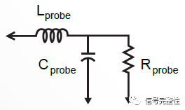
Figure 3: Basic Circuit of the Probe
To access probing points that are too tight in the surrounding environment, it may be necessary to find ways to add long leads or wires. However, adding accessories or probes to the probe will reduce bandwidth and increase loading effects, leading to a non-flat frequency response.
Use the shortest leads possible to maintain the probe’s bandwidth and accuracy. Generally, the longer the input line or lead of the probe, the greater the reduction in bandwidth. Narrow-bandwidth measurements may not be significantly affected, but when making wide-bandwidth measurements, especially above 1 GHz, careful selection of the probe and accessories used is essential. As the probe bandwidth decreases, you will lose the ability to measure fast rise times. Figure 4 demonstrates how the rise time displayed on the oscilloscope slows down as the length of the accessories increases. For the most accurate measurements, it is best to use the shortest probe possible.
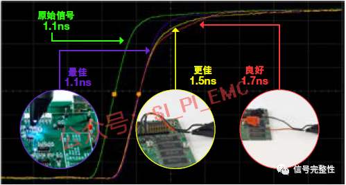
Figure 4: Probe Loading Effects Corresponding to Different Lead Lengths
Additionally, it is best to use shorter ground leads because the longer they are, the more inductance is introduced. Keep the ground lead as short as possible and as close to the system ground point as possible to ensure repeatable and accurate measurements.
Tip: If you must add wire to the probe to reach hard-to-reach probing points, it is best to add a resistor to the probe to dampen the resonance caused by the added wire. When adding long leads, you may not be able to resolve bandwidth limitation issues, but you can flatten the frequency response. To determine the size of the resistor to be used, you can probe a known square wave, such as the reference square wave provided on the oscilloscope. If the resistor is set correctly, you will see a clean square wave (except that its bandwidth may be limited). If the signal rings, increase the size of the resistor. For single-ended probes, only one resistor needs to be added at the probe. If you are using a differential probe, add a resistor to each lead.
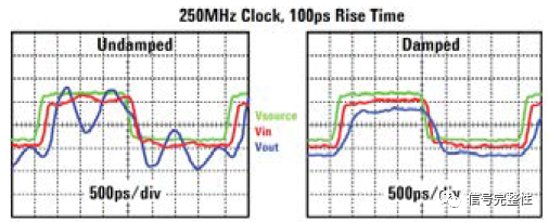
Figure 5: Adding a Resistor to the Probe Can Overcome Resonance Caused by Long Probe Connections, Reducing Ringing and Overshoot. However, It Cannot Solve Bandwidth Limitations Caused by Adding Leads.
Error 3: Not Fully Utilizing Your Differential Probe
Many people think that differential probes are only used for probing differential signals. Can differential probes also be used for single-ended signals? The answer is yes. If used effectively, this can save a significant amount of time and money in testing and improve measurement accuracy. Maximize the use of differential probes to achieve the best signal fidelity.
Differential probes can perform the same measurements as single-ended probes, and because differential probes have common-mode rejection on both inputs, the noise in differential measurements is greatly reduced. This allows you to see a better representation of the device under test’s signal without being misled by the random noise introduced by probing.
Figure 6 shows the blue single-ended measurement signal, while Figure 7 shows the red differential measurement signal. The blue single-ended measurement results have significantly more noise compared to the red differential measurement results, as the single-ended probe lacks common-mode correction capabilities.
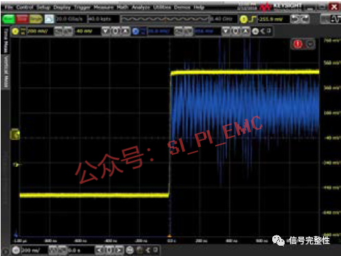
Figure 6: Single-Ended Measurement
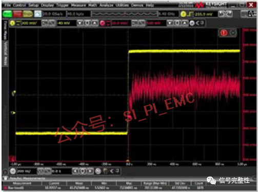
Figure 7: Differential Measurement
Error 4: Choosing the Wrong Current Probe
Large current and small current measurements require different levels of detail to be captured. Engineers need to know which current probe is more suitable for their application and what troubles may arise from using the wrong probe.
Large Current Measurement
If a clamp probe is used to measure large currents (10A – 3000A), the device under test must be small enough for the clamp probe to fit around it. If the device is too large for the clamp probe to fit, the engineer may try to add extra wires to the probe clamp, but this will change the characteristics of the device under test. A better approach is to use the right tool.
The best solution is to use a large current probe with a flexible loop probe front end. This flexible loop can be wrapped around any device. This type of probe is called a Rogowski coil. It allows engineers to probe devices without adding unknown characteristic components, maintaining high signal integrity in the measurement results. They also enable engineers to measure large currents from mA levels to hundreds of kA. Note that they only measure AC current, so the DC component will be isolated. Their sensitivity is also lower than some current probes. This is typically not an issue for large current measurements. However, when measuring small currents, sensitivity and the ability to view DC components become crucial. Remember that a method effective for one measurement may not be suitable for another.
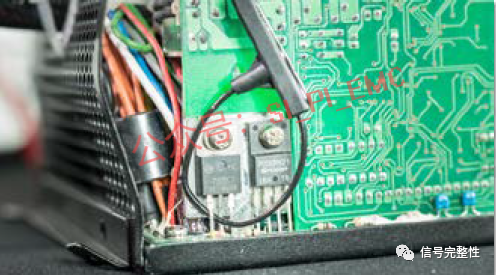
Figure 8: Rogowski Probe Wrapped Around a Component
Small Current Measurement
If measuring the current of battery-powered devices, the dynamic range can vary significantly. If the battery-powered device is idle or only handling a small number of background tasks, its current peaks will be very small. When the device switches to a more active state, the current peaks will increase significantly. Using a larger vertical scale setting on the oscilloscope, engineers can measure large signals, but small current signals will be masked by measurement noise. On the other hand, if you use a smaller vertical scale setting, large signals will clip, and measurement results will be distorted and invalid.
The selected current probe should not only be able to measure a wide range from μA to A but also allow viewing small current deviations using multiple amplifiers simultaneously. Two variable gain amplifiers in the probe allow you to set the amplified view to observe small current fluctuations while also zooming out to view large current spikes simultaneously (see Figure 9).
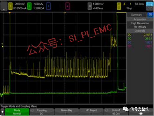
Figure 9: Current Probe with Two Variable Gain Amplifiers Allows You to View Small and Large Current Deviations Simultaneously
Error 5: Incorrectly Handling DC Offset During Ripple and Noise Measurements
Ripple and noise on a DC power supply are formed by small AC signals on top of a larger DC signal. When the DC offset is large, a larger vertical voltage setting may be needed on the oscilloscope to display the signal on the screen. Doing so reduces measurement sensitivity and increases noise compared to small AC signals. This means that an accurate representation of the AC portion of the signal cannot be obtained during testing.
If a DC-blocking capacitor is used to resolve this issue, it will inevitably block some low-frequency AC content, preventing engineers from observing changes in the signal as it passes through components in the device.
Using a power probe with a large offset capability allows the waveform to be centered on the screen without removing the DC offset. This lets the entire waveform be displayed on the screen while keeping the vertical scale small and in an amplified state. With these settings, details of transients, ripple, and noise can also be observed.
Error 6: Unknown Bandwidth Limitations
When making critical measurements, it is essential to choose a probe with sufficient bandwidth. Insufficient bandwidth can distort signals, making it difficult for engineers to make informed engineering tests or design decisions.
The generally accepted bandwidth calculation formula is: when measuring the rise time from 10% to 90%, bandwidth multiplied by rise time equals 0.35.
BW x Tr = 0.35
It is important to note that the bandwidth of the entire system is also a significant factor to consider. Both the probe and the oscilloscope’s bandwidth must be taken into account to determine the system bandwidth. The formula for calculating system bandwidth is as follows.
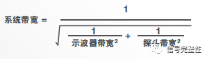
For example, suppose both the oscilloscope and probe have a bandwidth of 500 MHz. Using the formula above, the system bandwidth would be 353 MHz. It can be seen that the system bandwidth is significantly reduced compared to the individual bandwidths of the probe and oscilloscope.
Now, if the probe bandwidth is only 300 MHz while the oscilloscope bandwidth remains at 500 MHz, applying the formula results in the system bandwidth further dropping to 257 MHz.
Error 7: Masked Noise Effects
The noise from the probe and oscilloscope can cause the noise of the device under test to appear larger. Choosing a probe with an appropriate attenuation ratio for the engineer’s application will reduce the noise added by the probe and oscilloscope. This allows engineers to obtain more accurate signals and see the device under test more clearly.
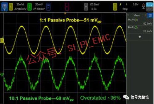
Figure 10: 50mVp-p Sine Wave Measured with 1:1 and 10:1 Probes
Many probe manufacturers describe probe noise as equivalent input noise (EIN) and express it in Vrms. A higher attenuation ratio allows you to measure larger signals, but the downside is that the oscilloscope will detect these ratios and simultaneously amplify the signal and its noise. To understand the practical result of this effect, the green trace in Figure 10 shows the noise amplified using a 10:1 probe.
Related Articles:
How to Make ADS a “Mobile Oscilloscope”[Insights] Connecting Simulation to Testing, Learn How to Connect ADS with Sampling Oscilloscope in One Article
How to Import Simulated Waveforms or Eye Diagrams into an Oscilloscope
Simulation Tells You: Can a 2-Port Network Analyzer Replace a 4-Port Network Analyzer?
S-Parameters to TDR (Impedance) — Network Analyzer “Transforms” into Sampling Oscilloscope
 |
 |