Recently, an engineer asked me how fast the highest toggle speed of an MCU can reach. I had heard about this topic years ago, but I had never actually tested it. This time, I took the opportunity to conduct some tests and discovered a lot of knowledge hidden within.
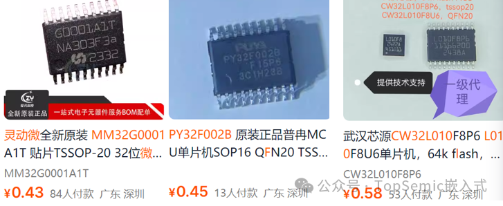
For this test, I selected three highly cost-effective 32-bit ARM Cortex-M0/M0+ core MCUs currently available on the market: the Lingdong Micro MM32G0001, the Puran PY32F002B, and the Xinyuan CW32L010, all priced under 50 cents!
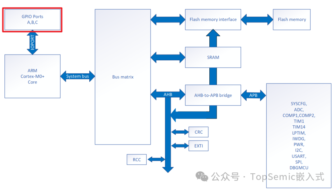
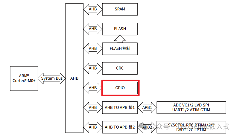
The first test was conducted on the Lingdong Micro MM32G0001 MCU, which is based on the ARM Cortex-M0 core and has a maximum operating frequency of 48MHz. The system architecture diagram is as follows:
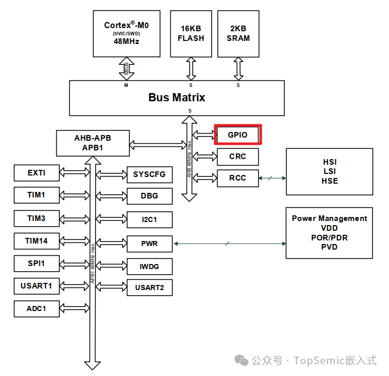
As can be seen, the GPIO module is located on the AHB bus, which has a maximum rate of 48MHz. The GPIO toggle involves switching between high and low levels, and executing a level control STR assembly instruction takes 2 instruction cycles. Therefore, theoretically, the maximum toggle rate of this MCU’s GPIO is 48MHz/(2+2)=12MHz. Now let’s look at the actual test results.
The test code is based on the example provided on the Lingdong Micro official website: LibSamples_MM32G0001_V0.10.2\Samples\LibSamples\GPIO\GPIO_LED_Toggle.
This example is configured to run at 48MHz. We will conduct the following experiments:
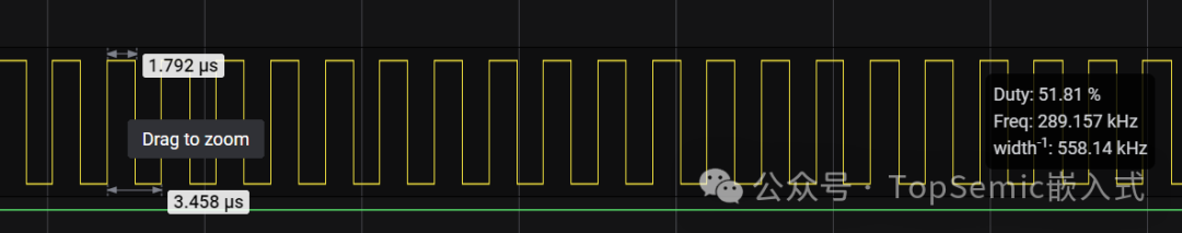
Experiment 1: Modify the original code by commenting out unrelated code, keeping only one GPIO toggle function in the while(1) loop.
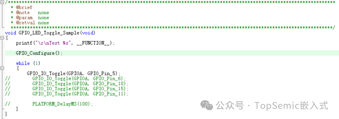
The test result was only 289kHz.
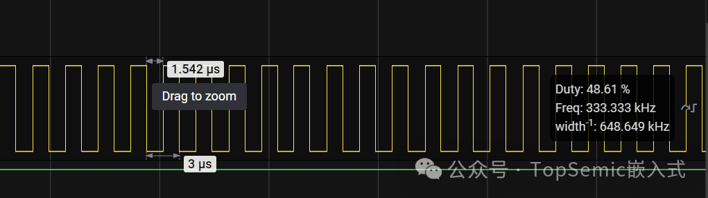
Experiment 2: Increase the optimization level from 0 to the highest:
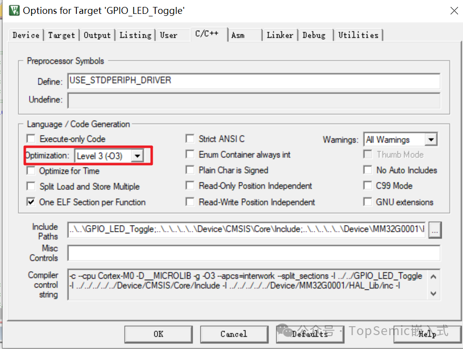
The test result was 333kHz.
The rates obtained from the above two experiments were far below the theoretical value, mainly due to the function calls, which consumed a lot of extra time.
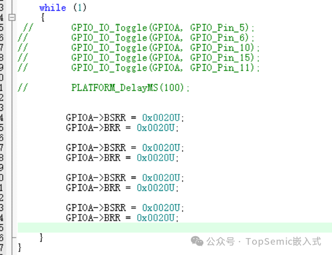
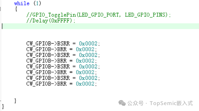
Experiment 3: This time, I directly modified the code to operate on the registers. To ensure consistency in testing, the optimization level was set back to 0.
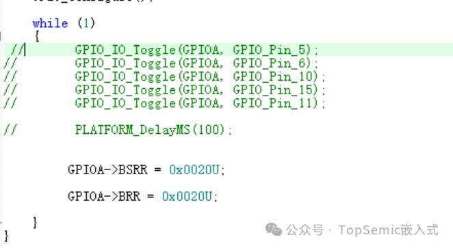
The result obtained was 4MHz, showing a significant improvement in speed.
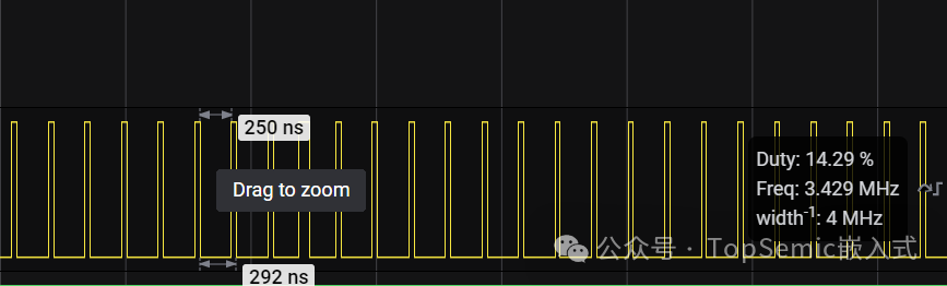
However, why is the low level time much longer than the high level time? After analysis, it was found that the while(1) loop occupied extra time.
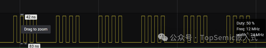
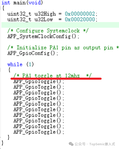
Experiment 4: Based on Experiment 3, I improved it by adding several repeated statements in the while(1) loop.
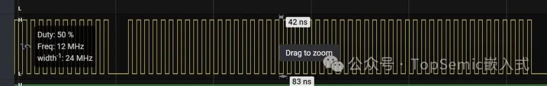
The test toggle rate was 12MHz, achieving the theoretical maximum rate.
The second test was conducted on the Puran PY32F002B MCU, which is based on the ARM Cortex-M0+ core and has a maximum frequency of 24MHz. The system architecture diagram is as follows:
It can be seen that the GPIO of this MCU is directly connected to the core, allowing for single-cycle fast toggling capability. Single-cycle GPIO is a feature uniquely supported by the ARM Cortex-M0+ core, which is not available in M0 core MCUs. Therefore, the maximum theoretical toggle rate of this MCU’s GPIO is: 24MHz/(1+1)=12MHz. Now let’s look at the actual test results.
The PY32F002B_Firmware_V1.1.0\Projects\PY32F002B-STK\Example_LL\GPIO\GPIO_FastIO directly provides a test example, which requires no modifications; just download it to test.
It can be seen that the IO toggle rate indeed reached 12MHz.
Although the maximum frequency of the PY32F002B is only half that of the MM32G0001, because it is directly connected to the core and has single-cycle toggling capability, both MCUs have a maximum IO toggle rate of 12MHz.
Finally, let’s look at the Xinyuan CW32L010 MCU, which is also based on the Cortex-M0+ core, but its GPIO is not directly connected to the core like the PY32F002B; instead, it is connected to the AHB bus. This MCU also has a maximum frequency of 48MHz.
With the above testing foundation, can you guess the maximum toggle rate of this MCU? You might think it is also 12MHz like the Lingdong Micro G0001. Is that really the case?
We made simple modifications based on CW32L010_StandardPeripheralLib_V1.0.2ExamplesGPIOgpio_blink, which by default runs at a frequency of 4MHz, changing it to 48MHz.
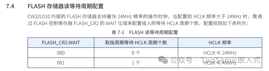
The actual test result was only 8MHz. What is the reason for this? We can see that the low level time is 2 instruction cycles, but the high level time is 4 instruction cycles.
This is due to Flash read wait states. When the main frequency exceeds 24MHz, a wait cycle needs to be inserted, so it cannot guarantee that each toggle can achieve 2 instruction cycles.
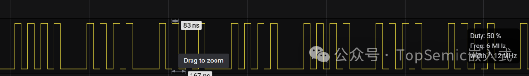
We can conduct another test by lowering the main frequency to 24MHz, and we can see that the GPIO toggle rate can reach 6MHz, as there are no Flash read wait states.
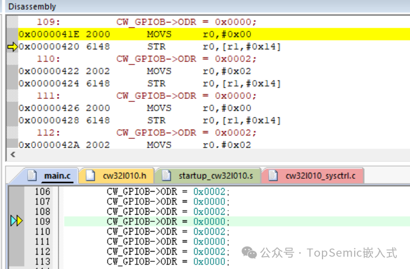
Finally, let’s conduct a test by modifying the GPIO toggle code slightly. The previous implementation used BSRR and BRR registers to set and clear the output. What effect would using the ODR register have?
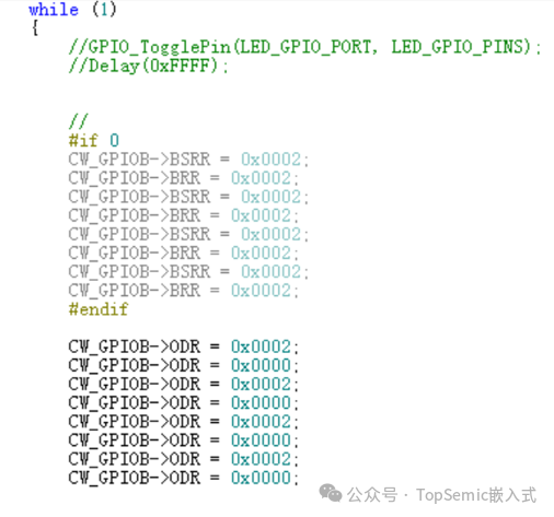
As can be seen, the toggle rate is only 4MHz.
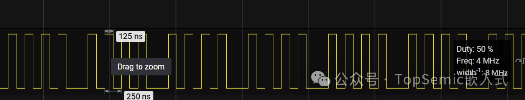
Through the assembly code, we can see that an additional MOVS instruction was added, which requires 1 instruction cycle, resulting in a maximum toggle rate of 24MHz/(3+3)=4MHz.
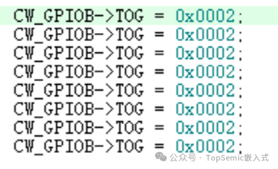
In addition to using set/clear registers and output data registers to implement GPIO toggling, some MCUs also have toggle registers. For example, the CW32L010 has one, while the MM32G0001 and PY32F002B do not. Using this single register can achieve IO toggling, and tests show that this effect is the same as using BSRR/BRR.
It can be seen that many factors affect the GPIO toggle speed of an MCU, including system clock frequency, whether single-cycle toggling is supported, Flash read wait states, the way toggle statements are written, and compiler optimization levels.
Finally, I leave a question for everyone to ponder: why can the Xinyuan CW32L010 and the Lingdong Micro MM32G0001 both run at a maximum frequency of 48MHz, yet the Xinyuan CW32L010 cannot reach the theoretical value of 12MHz while the Lingdong Micro MM32G0001 can? Feel free to leave your thoughts in the comments.
Previous Recommendations
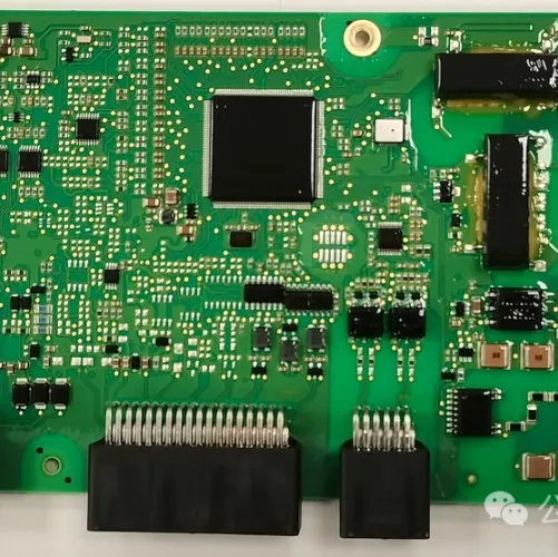
Detailed Analysis: A Comprehensive Review of the Wanjie M5 Battery Pack BMS Control Board, High and Low Voltage Circuit Analysis
2025-01-12
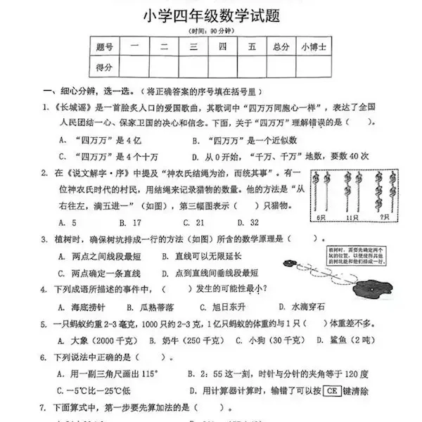
Electronic Engineers, can you solve a fourth-grade math problem?
2025-01-10
The Final Frenzy: The U.S. Plans to Restrict Global AI Chips in Three Tiers
2025-01-10

The “Wenzhou Shoe King” Crosses into the Semiconductor Dream, Stock Price Drops to Limit After Resuming Trading
2025-01-09

HDMI 2.2 and DP 2.1b New Interfaces Released Simultaneously! Bandwidth Approaching 100Gbps
2025-01-08