1. Configuration of FIR IP in Vivado

2. Setting up the simulation environment with Vivado and Modelsim
1. Configuration of FIR IP in Vivado
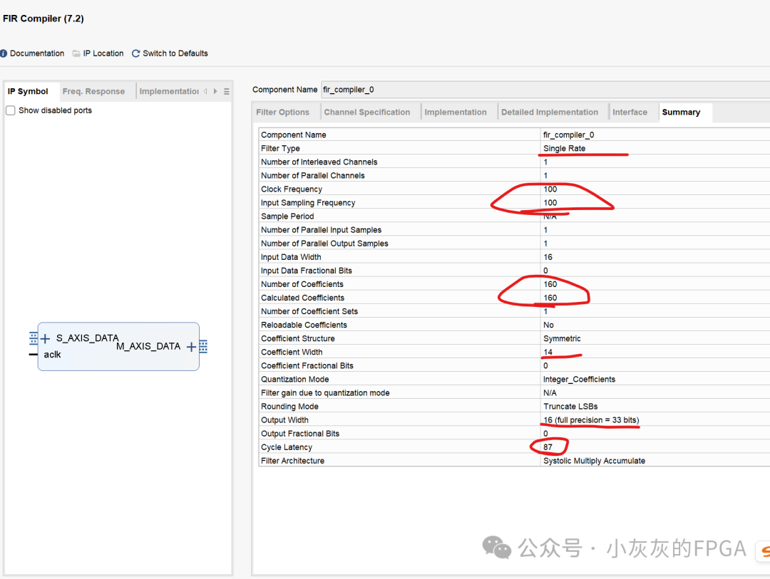
Vivado provides FIR IP for implementing low-pass filter FIR functionality. For specific details, please refer to the corresponding official manual. Here, we will briefly introduce the configuration interface of the FIR IP. The following image includes the import of the filter coefficient file (.coe) and the selection of the filter type as single rate. The filter coefficient file is generated by Matlab software in the previous chapter, containing the quantized FIR filter coefficients that meet the design requirements.
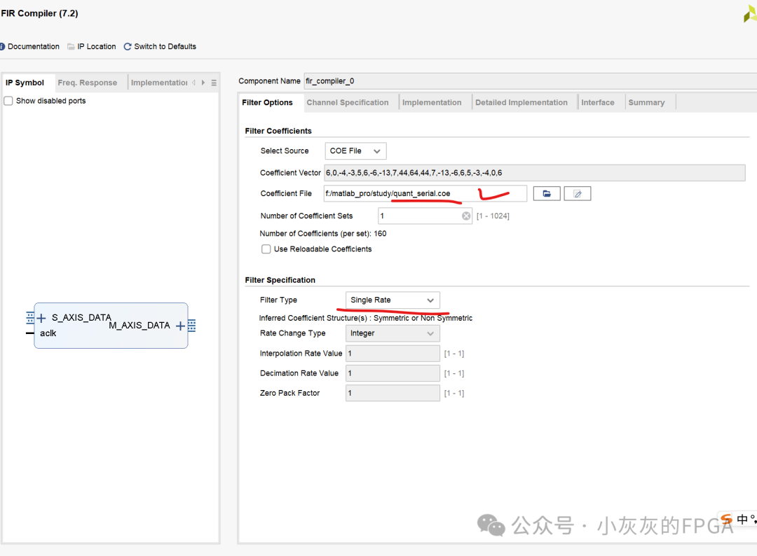
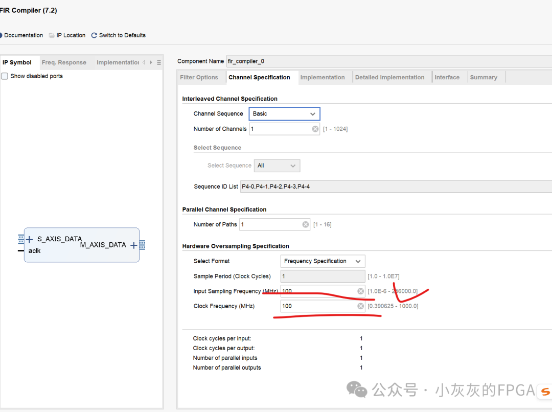
The sampling frequency used is 100MHz, which should also be consistent with the input sampling frequency of the signal in Matlab and the sampling frequency at which the FIR filter coefficients are generated.
The bit width of the quantized coefficients should be consistent with the configuration of the quantized FIR filter coefficients generated in Matlab, which is the quantization bit width of the .coe file imported into the Vivado FIR IP. The input signal bit width should be consistent with the mixed signal quantization bit width of 16 bits and should be of signed data type. The output selection can be configured according to the official manual from Xilinx.
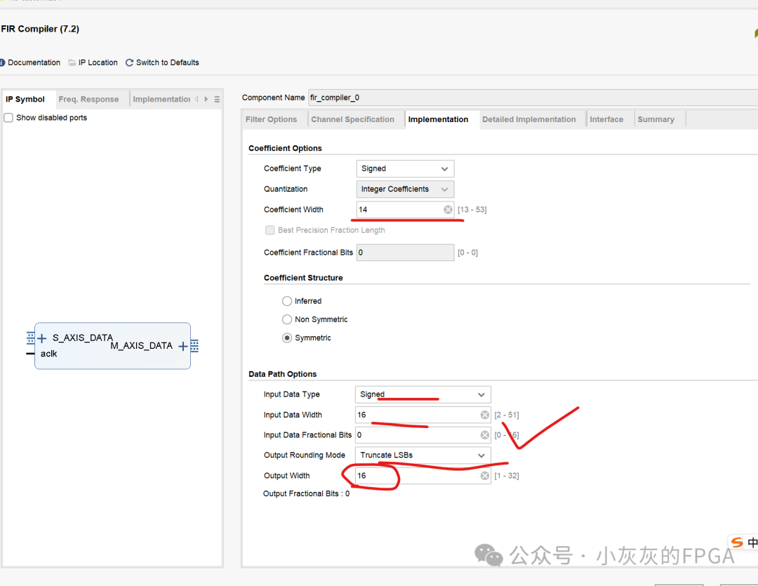
Finally, the configuration of the FIR IP is generated with a sampling frequency of 100MHz and a filter order of 160, consistent with the FIR filter order designed in Matlab. The quantization bit width is 14 bits, and the data output bit width is selected as 16 bits. It is important to note that the data output is delayed by 87 cycles, reflecting the processing interval of the FIR IP.
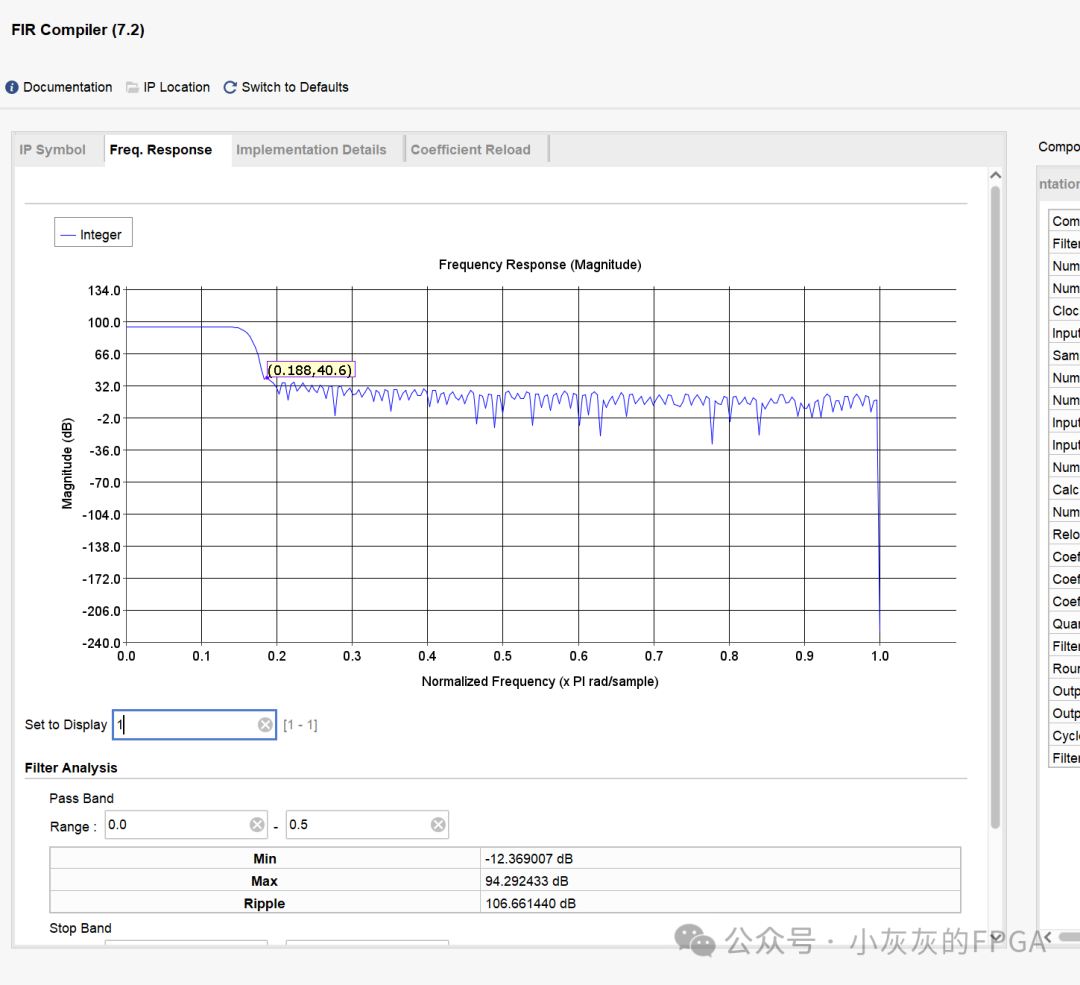
The frequency response of the FIR shows that there is indeed some error after quantization, especially with a stopband attenuation of 40.6dB.
2. Setting up the simulation environment with Vivado and Modelsim
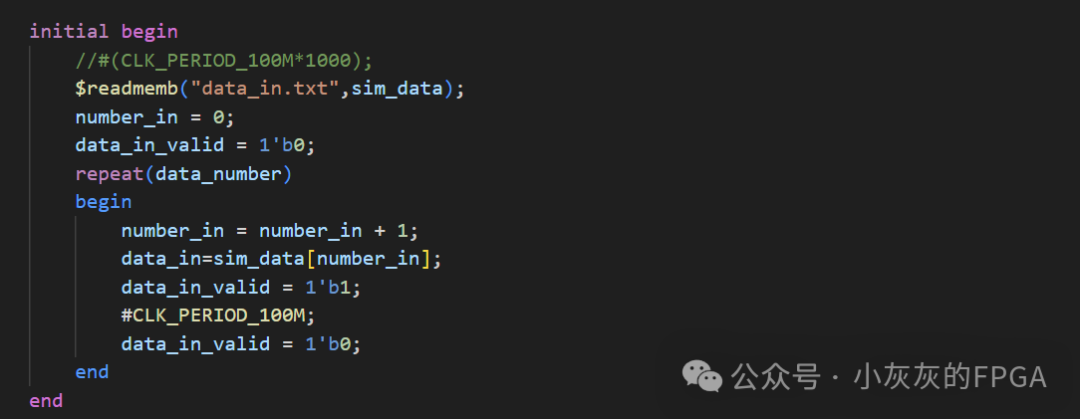
To build a joint simulation verification environment in Vivado and Modelsim, it is necessary to read the binary file data_in.txt for input simulation. The data_in.txt file should be placed in the local simulation path of Modelsim. The binary file is read using readmemb, and the data is input to the FIR IP core’s axistream interface when valid.
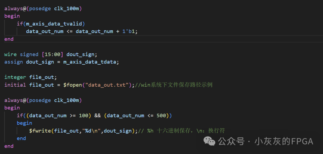
Data is stored at the output interface of the Vivado FIR IP, which is the data processed by the low-pass filter. Data can be stored over a certain period of time, using a counter to ensure the output data delay time. The saved data file will be used for later verification in Matlab.
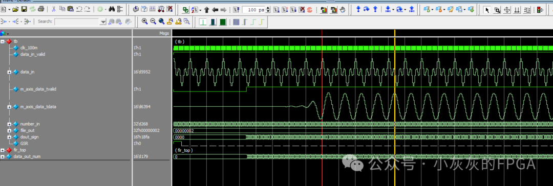
In Modelsim, the simulation data verification shows that after the mixed signal input, the output from the FIR IP is a single-tone signal. The period of the single-tone signal can be roughly estimated through time. This will not be displayed here, as frequency spectrum analysis will be conducted later using Matlab’s FFT.