In automation control, analog signals are ubiquitous. Whether it is temperature, pressure, flow, or even position signals, they can be converted into voltage or current analog signals. As a type of continuously variable input signal, accurately measuring and converting analog signals is the foundation of an excellent control system. Mastering a reliable method for analog signal processing is crucial for subsequent program development.
This article takes the processing of analog input signal values for the S7-1200/1500 as an example to introduce a relatively complete algorithm. For the S7-1200/1500 analog input/output specification document, refer to: A comprehensive article on Siemens PLC from analog signals to speed.
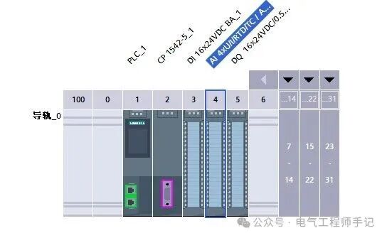
The PLC device configuration is as follows:
 Analog input/output moduleAI 4xU/I/RTD/TC/ AQ 2xU/I ST (6ES7534-7QE00-0AB0) wiring diagram is as follows:
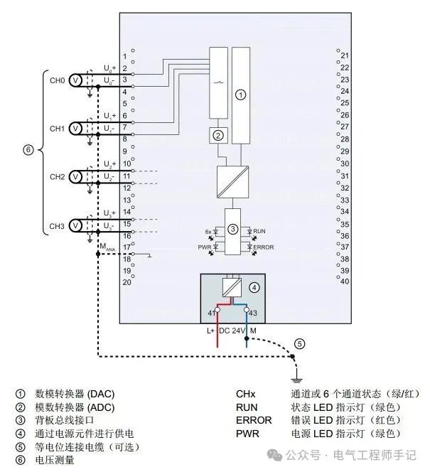 Analog input/output moduleschematic diagram is as follows: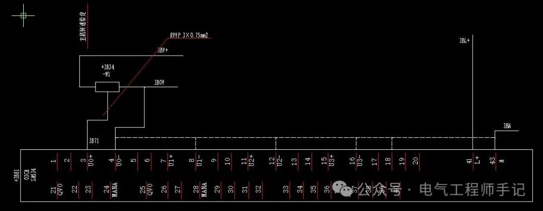
Analog input signal conversion value processing and detailed explanation:
Everyone has likely experienced that due to different power supplies and selected potentiometers for analog signals, it is common to encounter situations where the analog voltage signal exceeds +10V, or the potentiometer has returned to zero but the analog reading does not return to zero. Next, we will address these two issues to standardize the analog processing.
First, we need to perform “clipping” processing on the analog input signal in the example, using thebasic instruction list’smath function LIMIT–set limit instruction.
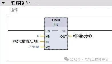
Limit the value of the analog signal input source IN to the range between input MN (Min) and MX (Max). If the input IN value meets the condition MN <= IN <= MX, it is directly output to OUT. If the condition is not met and the input value IN is below the lower limit MN, the output OUT is set to the value of input MN. If it exceeds the upper limit MX, the output OUT is set to the value of input MX. Here, it is important to note that if the value of input MN is greater than the value of input MX, the result will be the specified value in the IN parameter and the output ENO will be set to 0.
Then, perform a “normalization” operation on the “clipped” parameter to obtain a standardized range value. Here, we use thebasic instruction list’sconversion operation NORM_X–normalization instruction.
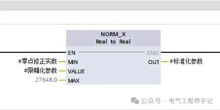
Map the value of the variable in the input VALUE to a linear scale for normalization. The linear scale uses parameters MIN and MAX to define the limits of the VALUE range. The result in OUT is calculated using the formula OUT = (VALUE – MIN) / (MAX – MIN) and is output as a floating-point number. If the value to be normalized equals the value in input MIN, the output OUT will be 0.0. If the value to be normalized equals the value in input MAX, the output OUT will be 1.0.Note, the introduction of a zero-point correction variable is to suppress the situation where the potentiometer returns to zero but the reading does not return to 0. In practical use, the reading after the potentiometer returns to zero can be parameterized as a constant or variable.
Finally, restore the “normalized” parameter using thebasic instruction list’sconversion operation SCALE_X–scaling instruction.
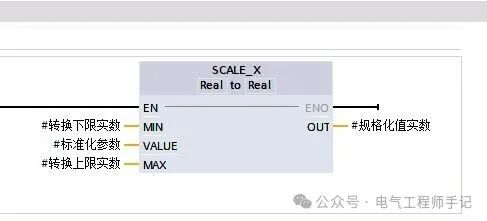 Map the value of the input VALUE to a specified value range and scale it. When executing the scaling instruction, the floating-point value of the input VALUE will be scaled to the value range defined by parameters MIN and MAX, calculated using OUT = [VALUE ∗ (MAX – MIN)] + MIN, and output in OUT. Since we want the normalization processing function to be applicable to different scenarios, the conversion parameters MIN and MAX are made variables to make the block function more flexible.
The complete Siemens S7-1200/1500 PLC analog normalization processingfunction block is as follows:
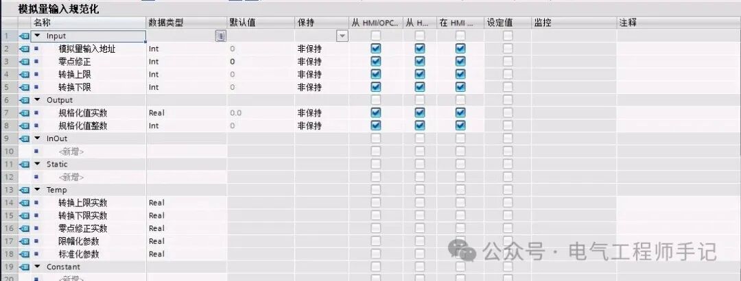
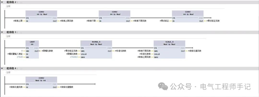
When calling, assign the analog input interface address at theanalog input address; thezero-point correction is parameterized based on the reading of the analog input interface address after the potentiometer returns to zero; theconversion upper limit andconversion lower limit are parameterized according to different application scenarios. In this example, the conversion is set to the PROFINET frequency converter’s set value, so the upper limit is 16384, which is 100%;The normalized output value is available in both real and integer data formats, from the same source.
The example program for calling is as follows:
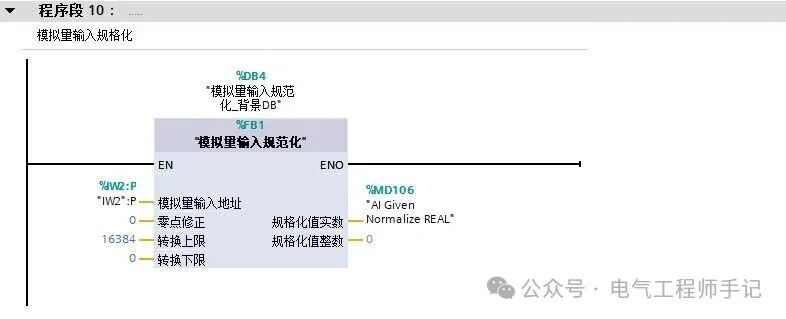
These are the steps and processes for analog normalization processing. Feel free to share your opinions and thoughts in the comments section.
Thank you for the likes ❤️, shares, and support.
Follow me to enter a world of pure practical knowledge in industrial control!
Example of using Siemens S7-1500 timer data blocks
Example of Siemens PLC multi-instance data blocks application
Example of custom PLC data types (UDT) application in Siemens S7-1500
Detailed explanation of S7-1200 PLC startup organization block OB100 and its application
How to set the power-off retention storage area for Siemens S7-1200 PLC?
Example of Siemens S7-1200 DeviceStates diagnostic function block programming
A comprehensive article on Siemens PLC from analog signals to speed
Two algorithms for calculating roll diameter using PLC (with formula suggestions for collection)
PLC programming methods for continuous length measurement with incremental encoders (suggested for collection)
Installation and authorization tutorial for Siemens TIA Portal V18 (with download link)
Installation package and authorization for Siemens TIA Portal V20 (with download link)