Click Blue Words To FollowServo and Motion Control
The above is an advertisement
|
1. Introduction 2. EtherCAT Operating Principles3. EtherCAT Technical Features |
3.10 EtherCAT Implementing Ethernet (EoE) 4. Infrastructure Costs5. EtherCAT Implementation6. Summary7. References |
1. Introduction
Fieldbus has become an integral component of automation technology, widely applied today through extensive practical experimentation and testing. The proliferation of fieldbus technology has enabled the widespread use of PC-based control systems. However, despite rapid advancements in controller CPU performance (especially in IPCs), traditional fieldbus systems have increasingly become a “bottleneck” in the performance development of control systems. Another factor necessitating technological innovation is that traditional solutions are not very ideal. The conventional approach, divided by layers, typically consists of several auxiliary systems (cyclical systems): actual control tasks, fieldbus systems, local extension buses or simple local firmware cycles of peripheral devices in the I/O system. Normally, the system response time is 3-5 times the controller cycle time. At the level above the fieldbus system (i.e., network controllers), Ethernet often represents the level of technological advancement to some extent. The latest technology in this area is applications at the drive or I/O level, which were previously dominated by fieldbus systems. These application types require the system to have good real-time capabilities, adapt to small data volume communications, and be cost-effective. EtherCAT can meet these demands and also implement internet technologies at the I/O level (see Figure 1).
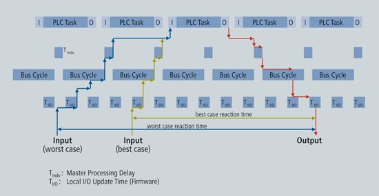 Figure 1: Traditional Fieldbus System Response Time
At the level above the fieldbus system (i.e., network controllers), Ethernet often represents the level of technological advancement to some extent. The latest technology in this area is applications at the drive or I/O level, which were previously dominated by fieldbus systems. These application types require the system to have good real-time capabilities, adapt to small data volume communications, and be cost-effective. EtherCAT can meet these demands and also implement internet technologies at the I/O level.
1.1 Ethernet and Real-Time Capability
Currently, there are many solutions striving to achieve real-time capabilities over Ethernet. For example, the CSMA/CD medium access control scheme prohibits higher-level protocol access and replaces it with time-slicing or polling methods; another solution is to allocate Ethernet packets by precisely controlling time through dedicated switches. While these solutions can quickly and accurately transmit packets to connected Ethernet nodes to some extent, the time required for output or drive controllers to redirect and read input data is constrained by the specific implementation method.
If a single Ethernet frame is used for each device, then theoretically, its usable data rate is very low. For example, the shortest Ethernet frame is 84 bytes (including the internal inter-frame gap IPG). If a driver periodically sends 4 bytes of actual values and status information, and simultaneously receives 4 bytes of command values and control words, then even with a bus load of 100% (i.e., infinitely small drive response time), its usable data rate can only reach 4/84 = 4.8%. If estimated with an average response time of 10 µs, the rate would drop to 1.9%. These limitations exist for any real-time Ethernet method sending Ethernet frames to each device (or expecting frames from each device), but the protocols used within the Ethernet frames are exceptions.
2. EtherCAT Operating Principles
EtherCAT technology breaks through the system limitations of other Ethernet solutions: with this technology, it is unnecessary to receive Ethernet data packets, decode them, and then copy process data to each device. EtherCAT slave devices read the corresponding addressing data as the message passes through their nodes, and similarly, input data is also inserted into the message as it passes through (see Figure 2). Throughout this process, the message experiences only a few nanoseconds of delay.
 Figure 2: Process Data Inserted into the Message
By compressing a large amount of device data in the sent and received Ethernet frames, the effective data rate can reach over 90%. The full-duplex characteristics of 100 Mb/s TX are fully utilized, allowing the effective data rate to exceed 100 Mb/s (i.e., greater than 2 x 100 Mb/s of 90%) (see Figure 3).
 Figure 3: Comparison of Bandwidth Utilization
The Ethernet protocol compliant with IEEE 802.3 standards can access each device without any additional bus. The physical layer of coupled devices can convert twisted pairs or fiber optics to LVDS (a selectable Ethernet physical layer standard), meeting the needs of modular devices such as electronic terminal blocks. This allows for very economical expansion of modular devices. Afterward, it can be converted from the baseboard physical layer LVDS to the 100 Mb/s TX physical layer at any time, just like regular Ethernet.
3. EtherCAT Technical Features
3.1 Protocol
EtherCAT is an optimized protocol for process data, capable of directly transmitting within Ethernet frames due to its special Ethernet type. An EtherCAT frame can include several EtherCAT messages, each serving a specific memory area of a logical process image that can be up to 4GB in size. The data order does not depend on the physical order of the Ethernet terminals in the network and can be arbitrarily addressed. Broadcasting, multicasting, and communication between slaves are all achievable. When optimal performance is required, and EtherCAT components and controllers operate within the same subnet, direct Ethernet frame transmission will be beneficial.
However, EtherCAT is not limited to applications within a single subnet. EtherCAT UDP encapsulates the EtherCAT protocol into UDP/IP datagrams, meaning that any Ethernet protocol stack can be addressed to the EtherCAT system, and communication can even be routed across subnets through routers. Clearly, in this variant structure, system performance depends on the real-time characteristics of the control and the implementation of the Ethernet protocol. Since UDP datagrams are unpacked only at the first station, the response time of the EtherCAT network itself is basically unaffected.
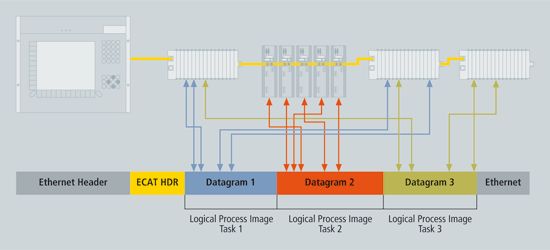 Figure 4: EtherCAT: Standard Frame Compliant with IEEE 802.3
Moreover, based on the master/slave data exchange principle, EtherCAT is also very suitable for communication between controllers (master/slave). Freely addressable network variables can be used for process data as well as parameters, diagnostics, programming, and various remote control services, meeting a wide range of application needs. The data communication interfaces between master/slave and master/master are also the same.
There are two mechanisms available for communication from slave to slave. One mechanism allows upstream and downstream devices to communicate within the same cycle, which is very fast. Since this method is topology-related, it is suitable for slave-to-slave communication determined by the device architecture design, such as printing or packaging applications. For freely configured slave-to-slave communication, the second mechanism can be adopted—data is relayed through the master. This mechanism takes two cycles to complete, but due to EtherCAT’s outstanding performance, the time taken is still faster than other methods.
According to literature, EtherCAT uses standard Ethernet frames without any compression. Therefore, EtherCAT Ethernet frames can be sent via any Ethernet MAC and can be monitored using standard tools.
3.2 Topology
EtherCAT supports almost any type of topology, including linear, tree, star, etc. (see Figure 5). The bus structure or linear structure named after the fieldbus can also be used for Ethernet and is not limited by the number of cascaded switches or hubs.
 Figure 5: Flexible Topology: Linear, Tree, or Star Topology
The most effective connection method for systems is to combine linear, branching, or tree structures in topology. Because the required interfaces already exist in many devices such as I/O modules, there is no need for additional switches. Of course, traditional Ethernet-based star topologies can still be used.
Different cables can also be selected to enhance connection flexibility: flexible, economical standard Category 5 Ethernet cables can transmit signals in 100BASE-TX mode; plastic fiber optics (PFO) can be used for special applications; and complete combinations of different Ethernet connections (e.g., different fiber optics and copper cables) can be achieved through switches or media converters.
The physical layer of fast Ethernet (100BASE-TX) allows a maximum cable length of 100 meters between two devices. Since the number of connected devices can be as high as 65,535, the network capacity is virtually unlimited.
3.3 Distributed Clock
Precise synchronization is particularly important for distributed processes that act simultaneously. For example, this is the case when several servo axes perform coordinated movements simultaneously.
The most effective synchronization method is to precisely arrange distributed clocks (see IEEE 1588 standard). Compared to situations where communication failures during fully synchronized communication immediately affect synchronization quality, distributed clock arrangements exhibit excellent fault tolerance to potential delays caused by related failures in the communication system.
With EtherCAT, data exchange is entirely based on pure hardware mechanisms. Because communication employs a logical ring structure (with the physical layer of full-duplex fast Ethernet), the master clock can simply and accurately determine the delay offsets of the clocks of each slave, and vice versa. Distributed clocks are adjusted based on this value, meaning that very precise, deterministic synchronization error time bases of less than 1 microsecond can be used across the network (see Figure 6). External synchronization such as cross-factory synchronization can be based on the IEEE 1588 standard.
 Figure 6: Synchronization and Consistency: Comparison of Two Distributed Systems 120 Meters Apart with 300 Nodes on an Oscilloscope
Additionally, high-resolution distributed clocks can not only be used for synchronization but also provide precise local time information for data acquisition. When sampling times are very brief, even a small instantaneous synchronization deviation in position measurement can lead to significant step changes in velocity calculations, such as when motion controllers calculate speed through sequential position detection. In EtherCAT, a timestamp data type is introduced as a logical extension, and the immense bandwidth provided by Ethernet allows high-resolution system times to be linked with measurement values. Thus, the precise calculation of speed is no longer affected by synchronization error values of the communication system, achieving higher accuracy than communication measurement techniques based on free synchronization errors.
3.4 Performance
EtherCAT has brought network performance to a new level. With the hardware integration of slave devices and direct memory access of the network controller master, the entire processing of the protocol is implemented in hardware, making it completely independent of the protocol stack, real-time operating system, CPU performance, or software implementation methods. The update time for 1,000 I/Os is only 30 µs, including the I/O cycle time (see Table 1). A single Ethernet frame can exchange up to 1486 bytes of process data, which is almost equivalent to 12,000 digital inputs and outputs, and the transmission of this data takes only 300 µs.
 Table 1: Overview of EtherCAT Performance
Communication for 100 servo axes is also very fast: all axes’ actual positions and states with command values and control data can be updated every 100 µs, with distributed clock technology ensuring that the synchronization deviation of the axes is less than 1 microsecond. Even with this performance guaranteed, the bandwidth is still sufficient for asynchronous communications, such as TCP/IP, downloading parameters, or uploading diagnostic data.
Ultra-high performance EtherCAT technology enables control concepts that traditional fieldbus systems cannot achieve. EtherCAT adapts communication technology to the supercomputing capabilities of modern industrial PCs, making the bus system no longer a bottleneck in control concepts, and distributed I/Os may operate faster than most local I/O interfaces. The principles of EtherCAT technology are flexible and are not bound to communication rates of 100 Mbps, and it may even be extended to 1000 Mbps Ethernet.
3.5 Diagnostics
Practical experience with fieldbus systems indicates that effectiveness and trial operation time critically depend on diagnostic capabilities. Only by quickly and accurately detecting faults and clearly indicating their locations can quick troubleshooting be achieved. Therefore, during the development of EtherCAT, particular emphasis was placed on strengthening diagnostic features.
During trial operation, the actual configuration of nodes such as drives or I/O terminals needs to match the specified configuration, and the topology also needs to match the configuration. Since the integrated topology identification process has extended to each terminal, this check can be performed not only during system startup but also during automatic network reading (configuration upload).
Data transmission errors can be effectively detected through CRC evaluation— the minimum Hamming distance of the 32-bit CRC polynomial is 4. In addition to line break detection and localization, the EtherCAT system’s protocol, physical layer, and topology can also monitor the quality of each transmission segment separately, and automatic assessments associated with error counters can accurately locate critical network segments. Moreover, for gradual or abrupt error sources such as electromagnetic interference, connector damage, or cable damage, even if they have not yet overstressed the network’s self-recovery capabilities, they can still be detected and localized.
3.6 High Reliability
Choosing redundant cables can meet the rapidly growing demand for system reliability, ensuring that device replacements do not lead to network failures. You can economically increase redundancy features by simply adding a standard Ethernet port at the master device end and converting a single cable from a bus topology to a ring topology (see Figure 7). When a device or cable fails, only one cycle is needed to switch. Therefore, even for applications requiring motion control, there will be no issues when a cable fails. EtherCAT also supports hot backup of master redundancy. When the loop is interrupted, the EtherCAT slave controller chip will immediately return the data frame, ensuring that the failure of one device does not lead to the collapse of the entire network. For example, drag chain devices can be configured in a branching topology to prevent cable disconnection.
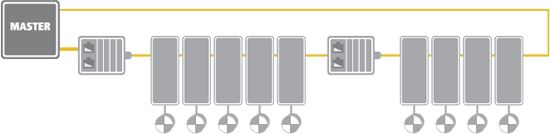 Figure 7: Low-Cost Cable Redundancy Using Standard Slave Devices
3.7 Safety
To achieve secure data communication over EtherCAT, the EtherCAT Safety Communication Protocol has been publicly released within the ETG organization. EtherCAT is used as a single channel for transmitting both safe and non-safe data. The transmission medium is considered a “black channel” and is not included in the safety protocol (see Figure 8). The safe data messages within EtherCAT process data include safe process data and required data backups. This “container” is safely parsed at the application layer of the device. Communication remains a single channel. This complies with the model A in IEC61784-3 annex.
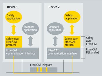 Figure 8: EtherCAT Safety Communication Software Component Using Black Channel
The EtherCAT Safety Protocol has been evaluated by the German Technical Supervisory Authority (TÜV SÜD Rail) as a communication protocol for transmitting process data between safety devices that meets the SIL3 level defined by IEC61508. Implementing the EtherCAT Safety Protocol on devices must meet the requirements of safety objectives. Corresponding product-related requirements must also be taken into account.
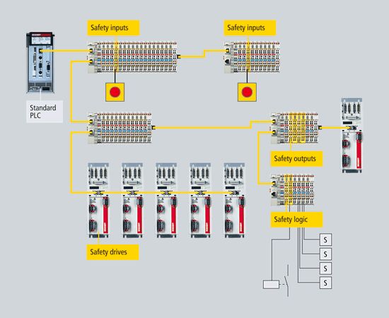 Figure 9: EtherCAT Safety System
The application example in Figure 9 benefits from this technology. Safe components can be used anywhere required in automation systems. Various sizes of local input and output components can be used in the system. Additional inputs and outputs can be expanded using safe or non-safe bus terminals based on demand. Safe logic is also embedded within the network. This allows standard PLCs without safety extensions to continue handling control tasks. The local safety logic required for safe input and output functions is implemented by intelligent safety bus terminals. This saves the costs associated with expensive safety PLCs and allows for flexible trimming of logical functions based on current tasks. Only the safety EtherCAT master and the assigned safety slaves are routed through non-safe standard PLCs.
-
This protocol has no restrictions on safe data length, communication medium, or baud rate.
-
EtherCAT is used as a “black channel,” meaning that the communication system has no role in safety processing.
-
The protocol is identified as compliant with the SIL3 level defined by IEC61508.
-
Products providing EtherCAT safety functions have been on the market since 2005.
3.8 EtherCAT Replacing PCI
As PC components rapidly miniaturize, the size of industrial PCs increasingly depends on the number of slots. The bandwidth of fast Ethernet and the process data length of EtherCAT communication hardware provide new possibilities for development in this field—traditional interfaces in IPCs can now be transformed into integrated EtherCAT interface terminals (see Figure 10). In addition to addressing distributed I/Os, addressing of drives and control units, fieldbus masters, fast serial interfaces, gateways, and other composite systems can also be achieved.
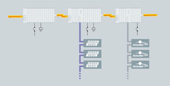 Figure 10: Distributed Fieldbus Interface
Even other Ethernet device variants without protocol restrictions can be connected via distributed switch port devices. Since a single Ethernet interface is sufficient for the communication of all peripheral devices (see Figure 11), this not only greatly simplifies the size and appearance of IPC hosts but also reduces the costs of IPC hosts.
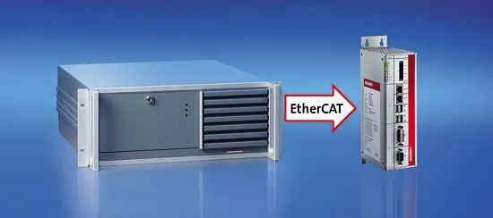 Figure 11: EtherCAT Significantly Reduces the Size of Controllers
3.9 Device Profiles
Device profiles describe the application parameters and functional characteristics of devices, such as machine states related to device categories. Fieldbus technology has provided usable device profiles for many device categories, including I/O devices, drives, valves, etc. Users are very familiar with these profiles and the associated parameters and tools, so EtherCAT does not need to redevelop device profiles for these categories but instead provides simple interfaces for existing device profiles. This feature allows users and device manufacturers to easily complete the transition from existing fieldbus technologies to EtherCAT technology.
3.9.1 EtherCAT Implementing CANopen (CoE)
CANopen© device and application profiles are widely used for various device categories and applications, such as I/O components, drives, encoders, proportional valves, hydraulic controllers, and application profiles for the plastics or textile industries. EtherCAT can provide the same communication mechanism as the CANopen mechanism, including object dictionaries, PDOs (Process Data Objects), SDOs (Service Data Objects), and even network management. Therefore, in devices already equipped with CANopen, EtherCAT can be easily implemented with minor modifications, allowing for the majority of CANopen© firmware to be reused. Moreover, optional extensions to objects can be made to take advantage of the immense bandwidth offered by EtherCAT.
3.9.2 EtherCAT Implementing Servo Drive Device Profile IEC 61491 (SoE)
The SERCOS interface™ is a globally recognized communication interface for high-performance real-time operating systems, especially suitable for motion control applications. The SERCOS™ framework for servo drives and communication technology falls under the IEC 61491 standard. This servo drive framework can be easily mapped to EtherCAT, with service channels embedded in drives, full parameter access, and functions based on EtherCAT mailboxes. Here, the focus remains on the compatibility of EtherCAT with existing protocols (IDN access values, attributes, names, units, etc.) and the extensibility related to data length limitations. Process data, which is in the form of AT and MDT SERCOS™ data, is transmitted using the EtherCAT slave controller mechanism, with mapping similar to the SERCOS mapping. Furthermore, the states of EtherCAT slaves can be very easily mapped to the states of the SERCOS™ protocol. The EtherCAT slave state machine can be easily mapped to the communication stages of the SERCOS™ protocol. EtherCAT provides advanced real-time Ethernet technology for this widely used device profile in the CNC industry. The advantages of this device profile, combined with the benefits provided by EtherCAT’s distributed clock, ensure precise clock synchronization across the network. Position commands, speed commands, or torque commands can be transmitted freely. Depending on the implementation, the same device configuration tools may even continue to be used.
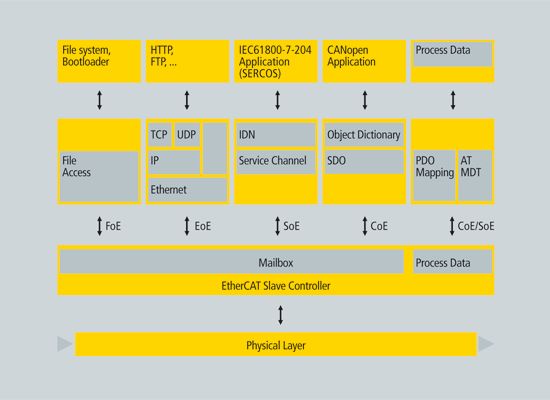 Figure 12: Multiple Device Profiles and Protocols Coexisting
3.10 EtherCAT Implementing Ethernet (EoE)
EtherCAT technology is not only fully compatible with Ethernet but also possesses good openness characteristics from the outset—this protocol can accommodate other Ethernet-based services and protocols within the same physical layer network, typically minimizing performance loss. There are no restrictions on the types of Ethernet devices; devices can be connected within the EtherCAT segment through switch ports. Ethernet frames are tunneled through the EtherCAT protocol, which is a common method used by internet applications such as VPN, PPPoE (DSL). The EtherCAT network is completely transparent to Ethernet devices, and its real-time characteristics remain undistorted (see Figure 13).
 Figure 13: Completely Transparent to All Ethernet Protocols
EtherCAT devices can accommodate other Ethernet protocols, thus possessing all the characteristics of standard Ethernet devices. The role of the master is similar to that of a layer 2 switch, redirecting Ethernet frames to the corresponding devices according to addressing information. Therefore, all internet technologies such as integrated web servers, email, and FTP transfer can be applied within the EtherCAT environment.
3.11 EtherCAT Implementing File Access (FoE)
This simple protocol is similar to TFTP, allowing access to any data structure within a device. Therefore, regardless of whether the device supports TCP/IP, standardized firmware can be uploaded to the device.
3.12 ADS over EtherCAT (AoE)
ADS over EtherCAT (AoE) is a client-server mailbox protocol defined by the EtherCAT specification. Although the CoE protocol provides detailed descriptions, AoE is more suitable for routing and parallel service applications: accessing sub-networks via gateway devices, such as EtherCAT to CANopen® or EtherCAT to IO-Link™ gateway devices. AoE allows EtherCAT master applications (such as PLC programs) to access various parameters of the associated CANopen® or IO-Link™ slaves. The overhead of the AoE routing mechanism is significantly lower than that defined by internet protocols (IP), and the sender and receiver addressing parameters are always included in the AoE message. Therefore, the implementation on both EtherCAT master and slave ends is more streamlined. AoE also standardizes non-periodic communication through the EtherCAT automation protocol (EAP), providing seamless communication between upper MES systems or main computers, EtherCAT masters, and existing devices under its jurisdiction. At the same time, AoE also provides a standardized method for retrieving EtherCAT network diagnostic information from remote diagnostic tools.
4. Infrastructure Costs
Since EtherCAT does not require hubs and switches, it can save investments in power supply, installation costs, and other equipment as long as environmental conditions permit, using only standard Ethernet cables and inexpensive standard connectors. If environmental conditions have special requirements, connectors with enhanced sealing protection levels can be used according to IEC standards.
5. EtherCAT Implementation
EtherCAT technology is developed for economical devices such as I/O terminals, sensors, and embedded controllers. EtherCAT uses Ethernet frames compliant with IEEE802.3 standards. These frames are sent by master devices, while slave devices only extract and/or insert data when the Ethernet frame passes through their location. Therefore, EtherCAT uses standard Ethernet MAC, which is a manifestation of its intelligence in master devices. Similarly, EtherCAT employs dedicated chips in slave controllers, which is also a manifestation of its intelligence in slave devices—regardless of the local processing capability or software quality, dedicated chips can handle process data protocols in hardware, providing optimal real-time performance.
5.1 Master
EtherCAT can achieve distributed process data communication of up to 1486 bytes in a single Ethernet frame. Other solutions generally require master devices to process, send, and receive frames for each node in every network cycle. The EtherCAT system differs in that, under normal circumstances, only one or two frames are needed per cycle to complete all communications for all nodes, so the EtherCAT master does not require a dedicated communication processor. The master function hardly burdens the host CPU, allowing it to easily handle these tasks while also managing applications, thus EtherCAT does not require expensive dedicated active plug-in cards, only passive NIC cards or motherboard-integrated Ethernet MAC devices are sufficient. EtherCAT master is easy to implement, especially suitable for small to medium-sized control systems and clearly defined application scenarios.
For example, if a single process image of a PLC does not exceed 1486 bytes, then it is sufficient to cyclically send this Ethernet frame during its cycle time. Since the message header does not change during operation, it is only necessary to insert the constant message header into the process image and transmit the result to the Ethernet controller.
EtherCAT mapping does not occur at the master but at the slave (peripheral devices insert data into the corresponding positions of the Ethernet frame they pass through), so at this point, the process image has already been sorted. This feature further reduces the burden on the host CPU. It can be seen that EtherCAT master is completely implemented in the host CPU using software, whereas traditional slow fieldbus systems require active plug-in cards to implement the master function, which occupies more resources, and even active cards serving DPRAM will consume considerable host resources.
System configuration tools (obtained from manufacturers) can provide network and device parameters, including the corresponding standard XML format startup sequence.
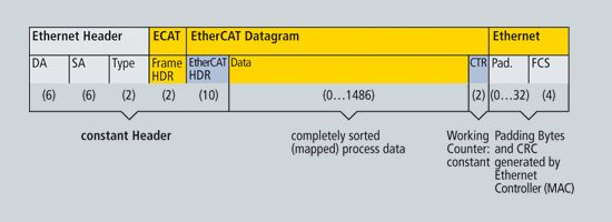 Figure 14: Single Process Image for Master Implementation
5.1.1 Master Implementation Services
EtherCAT masters have been implemented on various real-time operating systems, including but not limited to: eCos, INtime, MICROWARE OS-9, MQX, On Time RTOS-32, Proconos OS, Real-Time Java, RT Kernel, RT-Linux, RTX, RTXC, RTAI Linux, PikeOS, Linux with RT-Preempt, QNX, VxWin + CeWin, VxWorks, Windows CE, Windows XP/XPE with CoDeSys SP RTE, Windows NT/NTE/2000/XP/XPE/Vista with TwinCAT RTE, Windows 7 and XENOMAI Linux.
Open-source master protocol stacks are available as sample code or commercial software. Various companies also provide implementation services on various hardware platforms. Rapidly growing supplier information can be found in the product area of the EtherCAT website.
5.1.2 Master Sample Code
Another way to implement EtherCAT masters is to use sample code, which is low-cost. The software is provided in source code form, including all EtherCAT master functions, even including EoE (EtherCAT Implementing Ethernet) functionality. Developers only need to match this code, which is applied in Windows environments, with the target hardware and the RTOS used. This software code has been successfully applied in multiple systems.
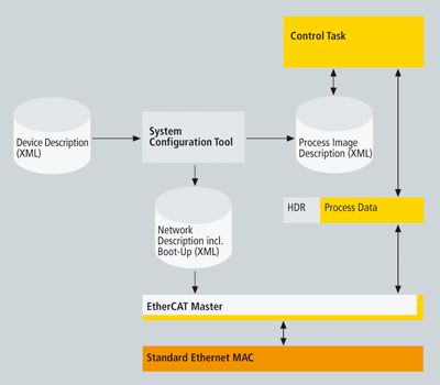 Figure 15: Structure of Master Sample Code
5.2 Slave
EtherCAT slave devices use a low-cost slave controller chip ESC. Slaves can achieve EtherCAT communication without a microprocessor. Simple devices that can be implemented through I/O interfaces can consist solely of ESC and its PHY, transformer, and RJ45 connector. The process data interface provided to slaves is a 32-bit I/O interface. This type of slave has no configurable parameters, thus no software or mailbox protocol is required. The EtherCAT state machine is handled by the ESC. The startup information of the ESC is read from EEPROM, which also supports slave identification. More complex configurable slaves use a CPU. This CPU communicates with the ESC via an 8-bit or 16-bit parallel interface or serial SPI interface. The required CPU performance depends on the slave’s application, with EtherCAT protocol software running on it. The EtherCAT protocol stack manages the EtherCAT state machine and application layer protocols, supporting CoE protocol and firmware download via FoE protocol. EoE protocol can also be implemented.
5.2.1 EtherCAT Slave Controller
Currently, multiple manufacturers provide EtherCAT slave controllers. The functionality of slave controllers can also be achieved through low-cost FPGAs, with licenses available for the corresponding binary code.
-
Slave controllers generally have an internal DPRAM and provide access to these application memory ranges:
-
Serial SPI (Serial Peripheral Interface) is mainly used for smaller process data devices such as analog I/O modules, sensors, encoders, and simple drives. This interface typically uses 8-bit microcontrollers, such as Microchip PIC, DSP, Intel 80C51, etc.
-
8/16-bit microcontroller parallel interfaces correspond to traditional fieldbus controller interfaces with DPRAM interfaces, especially suitable for larger data volume complex devices. Typically, microcontrollers used include Infineon 80C16x, Intel 80×86, Hitachi SH1, ST10, ARM, and TI TMS320 series.
-
The 32-bit parallel I/O interface can connect up to 32 digital inputs/outputs and is also suitable for 32-bit data operations of simple sensors or actuators. This type of device does not require a host CPU.
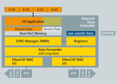 Figure 16: Slave Hardware: FPGA with Host CPU
 Figure 17: Slave Hardware: FPGA with Direct I/O
For the latest information on EtherCAT slave controllers, please visit the EtherCAT website.
5.2.2 Slave Evaluation Toolkit
Beckhoff’s Slave Evaluation Toolkit simplifies interface operation. With EtherCAT, there is no need for a powerful communication processor, so an 8-bit microprocessor can be used as the host CPU in the Slave Evaluation Toolkit. The toolkit also includes slave host software in source code form (equivalent to the protocol stack) and a reference master software package (TwinCAT).
6. Summary
EtherCAT boasts outstanding communication performance, very simple wiring, and openness to other protocols. Traditional fieldbus systems have reached their limits, while EtherCAT has established new technical standards—updating 1,000 I/O data within 30 µs, using twisted pairs or fiber optics, and achieving vertical optimized integration utilizing Ethernet and internet technologies. With EtherCAT, simple linear topologies can replace expensive star Ethernet topologies without the need for costly infrastructure components. EtherCAT can also utilize traditional switch connections to integrate other Ethernet devices. Other real-time Ethernet solutions require special connections to controllers, while EtherCAT only requires inexpensive standard Ethernet cards (NICs) to achieve this.
EtherCAT supports various mechanisms for communication from master to slave, slave to slave, and master to master (see Figure 18). It implements safety functions using technically feasible and cost-effective methods, allowing Ethernet technology to extend down to the I/O level. EtherCAT’s superior functionality is fully compatible with Ethernet, embedding internet technology into simple devices while maximizing the immense bandwidth provided by Ethernet, making it a real-time performance superior and cost-effective network technology.
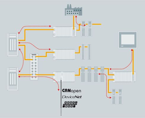 Figure 19: Diverse Network Structures
7. References
[1] EtherCAT Technology Group (ETG)
http://www.ethercat.org
[2] IEC 61158-3/4/5/6-12 (Ed.1.0), Industrial communication networks – Fieldbus specifications – Part 3-12: Data-link layer service definition – Part 4-12: Data-link layer protocol specification – Part 5-12: Application layer service definition – Part 6-12: Application layer protocol specification – Type 12 elements (EtherCAT)
[3] IEEE 802.3: Carrier Sense Multiple Access with Collision Detection (CSMA/CD) Access Method and Physical Layer Specifications
[4] IEEE 802.3ae-2002: CSMA/CD Access Method and Physical Layer Specifications: Media Access Control (MAC) Parameters, Physical Layers, and Management Parameters for 10 Gb/s Operation
[5] ANSI/TIA/EIA-644-A, Electrical Characteristics of Low Voltage Differential Signaling (LVDS) Interface Circuits
[6] IEEE 1588-2002: IEEE Standard for a Precision Clock Synchronization Protocol for Networked Measurement and Control Systems
[7] EN 50325-4: Industrial communications subsystem based on ISO 11898 (CAN) for controller-device interfaces. Part 4: CANopen
[8] IEC 61800-7-301/304 (Ed.1.0), Adjustable speed electrical power drive systems – Part 7-301: Generic interface and use of profiles for power drive systems – Mapping of profile type 1 to network technologies – Part 7-304: Generic interface and use of profiles for power drive systems – Mapping of profile type 4 to network technologies
[9] SEMI E54.20: Standard for Sensor/Actuator Network Communications for EtherCAT.
Source:
https://www.ethercat.org/cn/technology.html#5.2.2
The above image is an advertisement
– END –
Popular Articles

Industrial Control Companies 2020 Annual Report


Xinjie Electric 2020 Annual Report

Leadray Intelligent Listed This Year

Kübler Launches New Encoders and Slip Rings