 ☞ This is the 13738th article published by Metal Processing (mw1950pub)

Editor’s Note
1 Introduction
Profibus-DP network is a widely used fieldbus technology for data communication and control in the automation system monitoring layer and lower layer. It represents the development of automation technology but often experiences communication interruptions during actual operation. If the situation involves a single station dropping out, it is relatively easy to handle. However, when the Profibus-DP network experiences communication interruptions, it is challenging to troubleshoot due to multiple potential causes, making it a persistent problem in this field. This article summarizes existing handling methods and presents a rapid troubleshooting method to identify interference sources or fault points based on the author’s years of field experience, using a wide-body production line as an example. The troubleshooting process and solutions will be detailed below.
2 Analyze the Site
By organizing the site topology network, it can be observed through software that the field network uses Profibus-DP: bus structure, baud rate 93.75kB/s. Determine the bus lengths between each station, review the electrical schematic, and find that the Profibus-DP network is divided into two paths. One path has the station addresses: CPU→Station 5→Station 19→Station 26→Station 10→Station 6→Station 25→Station 9→Station 27, with Station 27 being the terminal, and the bus length is 71m; the other path has the addresses: PLC→HMI→Station 8→Station 13→Station 12→Station 16→Station 15→Station 4→Station 14→Station 24→Station 17→Station 18→Station 3→Station 7→Station 21→Station 22→Station 11, with Station 11 being the terminal, and the bus length is 151m. The bus length can also be diagnosed using ProfiTrace (baud rate ≥ 500kB/s), where Stations 26 and 27 are robot stations; Stations 12 to 19, 21, 22, and 25 are SMC stations, with communication and power connectors being M12 and the communication module being EX260-SP1; HMI is Siemens MP277 touchscreen, with station address 30, baud rate 93.75kB/s; CPU is 315-2DP, model 315-2AH14-0AB0; other stations are Siemens ET200 stations, model 6ES7153-1AA03-0XB0, with communication connectors being 6ES7 972-0BB52-0X A0, using blade crimping wiring. The total length of the communication bus on site is approximately 222m, with a total of 25 stations. When the number of Profibus slaves exceeds 32, an RS 485 repeater needs to be added.
When using or adjusting, it is essential to confirm the basic wiring and communication principles of all hardware. Based on the first step of organization, the main hardware on site includes PLC, touchscreen, ET200, DP, M12 communication, and power connectors. Additionally, the following three points need to be particularly noted.
1) Differentiate the terminal resistance connection method of Siemens DP connector 6ES7 972-0BB12-0XA0 (see Figure 1) from that of SMC EX260-SP1 (see Figure 2). The Siemens DP connector in the ON position indicates that A1 and A2, B1 and B2 are disconnected, with the incoming line A1, B1 grounded with a 390Ω ground resistor; the Siemens DP connector in the OFF position indicates that A1 and A2, B1 and B2 are connected. The SMC valve island connects A1 and A2, B1 and B2, and the ON/OFF position of the terminal resistor indicates whether the terminal resistor is connected. The function of the terminal resistor is to absorb reflected waves; therefore, it is essential to understand the significance of each terminal resistor when diagnosing the stations.
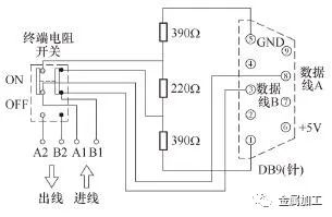
Figure 1: Siemens DP Connector Terminal Resistance Connection Method
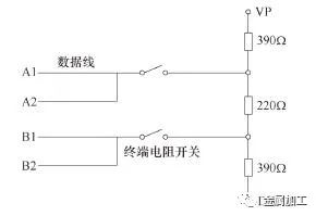
Figure 2: SMC EX260-SP1 Terminal Resistance Connection Method
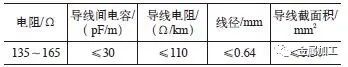
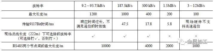
2) Pay attention to the technical parameters of the corresponding twisted shielded wire used for communication with Profibus-DP (see Table 1), especially in places with long usage years and severe electromagnetic radiation, such as welding workshops and highly corrosive chemical workshops.
Table 1: Technical Parameters of Profibus-DP Twisted Shielded Wire
3) In a non-grounded structure, pay attention to the number of IM153-X among the connected slaves. A single power supply can operate a maximum of 18 nodes on Profibus-DP. If there are more than 18 nodes, an additional power supply must be used.
3 Calculate Network Cycle Time
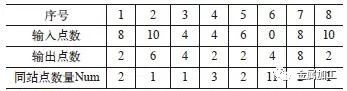
The I/O configuration of the site stations is shown in Table 2. Referencing Table 2, the minimum cycle time for data information is calculated as follows: ΣTTC=(TSYN+TID1+TSDR+Header+Number of Input Points×11Bit+Number of Output Points×11Bit)×Num1+(TSYN+TID1+TSDR+Header+Number of Input Points×11Bit+Number of Output Points×11Bit)×Num2+…+(TSYN+TID1+TSDR+Header+Number of Input Points×11Bit+Number of Output Points×11Bit)×Num8=9117Bit=8.9033kB. Here, TSYN is the information cycle time calculated by bits; TID1 is the idle time on the master station, which is 75 time bits; TSDR is the delay time at the slave station, which is 11 time bits; and Header is the message header size in request and response frames, which is 198 time bits.
Table 2: I/O Configuration of Site Stations (Unit: Pieces)
Based on the current baud rate of 93.75kB/s, the time needed to transmit 9117Bit is t=1÷93.75kB/s×8.9033kB=94.97ms. The monitoring time for the scan cycle is 150ms, and the load percentage of the scan cycle from communication is 20%, which is 30ms. Therefore, if the time required for transmission exceeds the set value, data loss or communication interruption may occur, necessitating that data transmission be completed within one scan cycle.
When adjusting, the following points should be noted.
1) When adjusting the transmission rate, it needs to be determined based on the length of the site topology network. The relationship between baud rate and transmission distance can be found in Table 3.
Table 3: Relationship Between Baud Rate and Transmission Distance
2) It is also essential to pay attention to the position of the touchscreen in the network and modify the touchscreen baud rate; otherwise, communication errors may occur.
3) If the site network length exceeds the maximum transmission value allowed by the adjusted baud rate, it is necessary to adjust the PLC parameter settings or both the PLC parameter settings and baud rate, or use a repeater for network isolation and topology.
4) This work should be carried out when there are no network faults to facilitate observation of the effects; the baud rate can be adjusted up to 500kB/s. Based on site confirmation, the time required to transmit 9117Bit is 17.8ms.
4 Diagnose Faulty Stations
Fault diagnosis can be roughly determined based on the alarm information from the hardware diagnostic buffer, identifying which stations or workstations frequently drop out. The following diagnostic methods can quickly pinpoint fault points.
(1) The first method is to lower the baud rate (see Table 3) to verify if the fault is related to signal attenuation; this is a direct and effective method.
(2) The second method is to implement network isolation, which can be achieved by adding repeaters to determine if the fault or interference point is within a specific network segment.
When implementing this method, the following points should be noted.
1) It is recommended to use a binary method for isolation while considering the location of the site network, avoiding increasing the length of the site network lines.
2) When isolating the network, pay attention to the position of the terminal resistors in each network segment.
3) During network isolation (see Figure 3), only connect one network in the isolated segment to avoid interference from the same source network (see Figure 4).
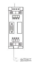
Figure 3: Network Isolation
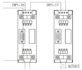
Figure 4: Same Source Network (Same Color Same Source)
4) Ensure that the spacing between RS485 nodes meets requirements.
5) When RS485 is grounded, all nodes should be grounded and connected between M and PE; when RS485 is not grounded, all nodes should not be grounded and not connected between M and PE, and the RS485 power supply should also be ungrounded. In the ungrounded operation mode, the built-in 22nF capacitor and 10MΩ resistor of the repeater can release interference currents and static charges.
6) In severe interference situations, ensure that each bus link has a terminal resistor at both the head and tail ends, especially at the first station after adding a repeater. In laboratory conditions, terminal resistors can be set only at the terminals.
(3) The third method is to use a multimeter or oscilloscope to measure, primarily focusing on measurement points.
1) Measure for short circuits between DP bus A/B phases, checking if A or B is shorted to the shield layer. It is recommended to use a binary method for measurement and be aware of interference issues from the same source network in Figure 4.
2) Measure the voltage of A/B relative to the shield layer; A should be around 2V and B around 2.4V, with the actual differential value during data transmission being around 3V. The following points need to be noted: First, when measuring the short circuit between A/B phases, the network and terminal resistors must be disconnected. Second, when measuring A/B phase voltages, measurements should be taken under voltage to avoid short circuits. Third, differentiate between measured voltage values and voltage values calculated using ProfiTrace for network diagnostics, as the voltage calculated by ProfiTrace is typically higher than the direct measurement with a multimeter. Fourth, if A/B is shorted to ground, the relative ground voltage is generally 0V.
3) Pay attention to the separation of zero ground in the distribution cabinet. If conditions allow, the grounding of power cables and control systems should be separated.
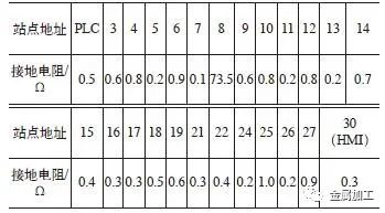
4) Measure the ground resistance of each station; the ground resistance should be less than 2Ω. Be sure to note any abnormal grounding resistance points (measured resistance values of stations can be found in Table 4). From Table 4, it can be seen that the resistance of Station 8 is abnormal, and grounding can be done separately. If the fault cannot be eliminated, consider the possibility of an ET200 module failure.
Table 4: Station Resistance Measurement Values
(4) The fourth method is to use ProfiTrace for network diagnostics, conveniently eliminating faulty stations. It can analyze the differential voltage between A/B phases (see Figure 5), dropout conditions, network structure, and waveforms. This will not be elaborated on here. For example, the communication voltage at Station 9 on site is unstable, easily causing data loss or dropouts. It is necessary to reconnect and tighten the wiring of the connector at Station 9, and consider replacing the DP connector with a wired 6ES7 972-0BB12-0XA0 while also checking if the ET200 station is damaged.
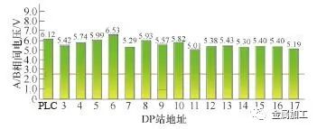
Figure 5: Differential Voltage Between A/B Phases
(5) The fifth method is to sequentially disconnect the terminal resistors starting from the first station of each network segment (see Figures 1 and 2), paying attention to the significance of terminal resistors at each station and module. This method is equivalent to short-circuiting each station one by one from the first station of each network segment, combined with the STEP7 hardware diagnostic buffer, to observe if the alarm status improves. The quality of the communication connectors should also be noted.
After excluding faults with the first and second methods, the network needs to be restored to its original state. After excluding faults with the third, fourth, and fifth methods, the network can be run directly.
5 Eliminate Interference
After the above diagnostics, both hardware and software faults have been eliminated, and other influencing factors primarily consider electromagnetic interference in the field environment. The following methods should be considered to eliminate electromagnetic interference.
(1) Use shielding to reduce electromagnetic interference. Shielded cables should be used for control lines, ensuring proper grounding of the shields. For high current power lines, it is best to use shielded cables and route them separately and independently from control cables.
(2) Use grounding techniques to eliminate interference, especially regarding motor grounding, inverter grounding, and control system grounding. The method of adding terminal resistors to absorb reflected waves is generally needed, where the first and last stations of the network require pull-up and pull-down resistors.
(3) Use wiring methods to reduce interference, mainly by separating control cables and power cables in cable trays.
(4) Use filters to reduce interference. If conditions permit, the control system can utilize purified power supplies and UPS, or add filters to the power system to improve power quality.
(5) Add magnetic rings to eliminate interference. Magnetic rings can be added at the connection points of DP cables.
6 Conclusion
Through the above process, a deep analysis of the system’s hardware (including network hardware structure, wiring, hardware brand models, and physical parameters of network stations), software (including parameter settings, bus time calculations, etc.), and electromagnetic interference (including grounding techniques, shielding, etc.) issues has been conducted. This provides guiding opinions for solving various issues such as DP communication alarms and interruptions on site, forming a systematic approach. Utilizing this systematic method not only significantly improves fault troubleshooting efficiency but also enhances the accuracy of locating fault points.
This article was published in Metal Processing (Cold Processing), Issue 8, 2021, pages 86-89. Authors: Huang Jingjing, Song Xianjin, Wang Lei, China National Heavy Duty Truck Group Co., Ltd.Original Title: Analysis and Handling of Profibus Communication Interruptions.
-End-
☞ Source: Metal Processing ☞ Edited by: Qinghe ☞ Media Cooperation: 010-88379864