Click on the top“Baiwen Technology”, select the top public account
Embedded essentials delivered promptly
——
Author | linuxdrivers
Source |
https://blog.csdn.net/linuxdrivers/article/details/5849698
A student suggested writing about PCI drivers, and today I found a long article that is one of the most detailed blogs on PCI available online. It is divided into two parts, and this is the first part, to be continued.
To understand Linux PCI device drivers, one must first realize that what is referred to as Linux PCI device drivers actually includes both the Linux PCI device driver and the driver for the device itself.
I don’t know if the readers understand this statement, but I think it’s very important. For drivers like PCI and USB, one must understand this concept to comprehend how to view PCI and USB under Linux as well as similar bus-type drivers. The reason is simple: the Linux PCI driver is built into the kernel, or in other words, the kernel has written it for you. What we need to complete is the driver for the device itself, such as a network card driver.
Of course, it doesn’t mean that since the kernel has written the Linux PCI driver for us, we don’t have to do anything. At the very least, you need to understand what the kernel has generally done so that you can understand what you need to do and how to complete the driver for the device itself.
This is similar to how we learn operating systems; we need to learn many system call interfaces. If we don’t understand these interfaces, how can we use the operating system or the functions it provides? So here we will study what the Linux PCI driver actually does, so that we can complete the driver for our device based on this understanding.
The article at http://tldp.org/LDP/tlk/dd/pci.html mentions:
Linux PCI initialization code logically divides into three parts:
(1) PCI Device Driver (the Linux PCI device driver mentioned above)
This pseudo-device driver queries the PCI system starting from bus 0 and locates all PCI devices and PCI bridges in the system. It establishes a linked list of data structures that can describe the topological hierarchy of this PCI system. It also numbers all discovered PCI bridges.
(2) PCI BIOS
This software layer provides services as described in the bib-pci-bios reduction. Although the Alpha AXP does not provide BIOS services, its Linux version includes the corresponding functionality.
(3) PCI Fixup
System-specific PCI initialization patch code
Here we mainly discuss the Linux PCI device driver, and at the end, we will list a segment of example code that includes the driver for the device itself, for reference only.
1. Overview and Introduction
PCI (Peripheral Component Interconnect) has three address spaces: PCI I/O Space, PCI Memory Address Space, and PCI Configuration Space. Among them, PCI I/O space and PCI memory address space are used by the device driver (the device driver mentioned above), while PCI configuration space is used by the Linux PCI initialization code, which is used to configure PCI devices, such as interrupt numbers and I/O or memory base addresses. Therefore, the PCI device driver here is meant to roughly describe what the Linux kernel has done for PCI device drivers (mainly), followed by what we should complete (secondarily).
(1) What the Linux Kernel Does
Simply put, the Linux kernel mainly enumerates and configures PCI devices; these tasks are completed during the Linux kernel initialization.
Enumeration: For the PCI bus, there is a device called the PCI bridge used to connect the parent bus to the child bus. As a special PCI device, the PCI bridge mainly includes the following three types:
(1). Host/PCI Bridge: Used to connect the CPU to the PCI root bus, with the first root bus numbered as 0. In PCs, the memory controller is often integrated into the Host/PCI bridge device chip, so the Host/PCI bridge is often referred to as the “North Bridge Chipset”.
(2). PCI/ISA Bridge: Used to connect the old ISA bus. Typically, devices like the i8359A interrupt controller are also integrated into the PCI/ISA bridge device. Therefore, the PCI/ISA bridge is often referred to as the “South Bridge Chipset”.
(3). PCI-to-PCI Bridge(hereinafter referred to as PCI-PCI Bridge): Used to connect the primary PCI bus and the secondary bus. The PCI bus in which the PCI-PCI bridge is located is called the primary bus, while the PCI bus connected by the PCI-PCI bridge is called the secondary bus, which is the child bus of the primary bus.
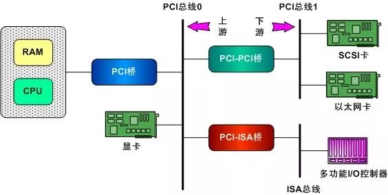
Figure 1, Schematic Diagram of PCI System
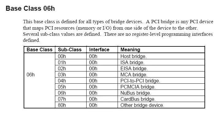
The diagram below is excerpted from the PCI Local Bus Specification Revision 2.1, where the Class Code of the PCI-PCI bridge (see Figure 3) is 0x060400.
The CPU is connected to a PCI bus through the Host/PCI bridge, and the PCI bus in this position is called the root bus. Typically, there is only one Host/PCI bridge in a PC, and based on one PCI bus, it can connect to other subordinate buses through PCI bridges, for example, another PCI bus can be connected through a PCI-PCI bridge, and an ISA bus can be connected through a PCI-ISA bridge.
In fact, the ISA bus in modern PCs is connected to the PCI bus through a PCI-ISA bridge. Thus, by using a PCI-PCI bridge, a hierarchical, tree-like PCI system structure is established. For the upper-level buses, the PCI bridges connected to these buses are also devices. However, this is a special device that is both a device on the upper-level bus and, in fact, an extension of the upper-level bus.
So-called enumeration is the process of probing and scanning starting from the Host/PCI bridge, “enumerating” all devices connected to the first PCI bus one by one and recording them. If any device is a PCI-PCI bridge, further probing and scanning will occur on the secondary PCI bus connected to this bridge. This process continues recursively until all PCI devices in the system are exhausted.
The result is the establishment of a PCI tree in memory representing these PCI buses and devices. Each PCI device (including PCI bridge devices) is represented by a pci_dev structure, while each PCI bus is represented by a pci_bus structure. You have a hardware device tree established through the PCI bridge, and I have a software tree constructed in memory through data structures, which is quite harmonious.
Configuration: PCI devices generally come with some RAM and ROM space, and the usual control/status registers and data registers often appear in the form of RAM ranges. These ranges are generally addressed from 0 within the device. When multiple devices are connected to the bus, accessing these spaces can lead to conflicts.
Therefore, these addresses must first be mapped to the system bus and then further mapped to the kernel’s virtual address space. The so-called configuration is accomplished by operating on the registers in the PCI configuration space to complete the address mapping (the task of mapping internal addressing to bus addresses is only the kernel’s job, while mapping to the kernel’s virtual address space is the job of the device driver itself).
(2) How the Linux Kernel Does It
Here, it is important to note that both the BIOS of the PC and the Linux kernel can perform PCI device initialization (i.e., the aforementioned enumeration and configuration tasks). Generally speaking, any PC using a PCI bus must have BIOS that provides support for PCI bus operations, hence referred to as PCI BIOS.
Moreover, the earliest Linux kernel also obtained information about PCI devices in the system through this BIOS call method, but not all platforms have BIOS (such as some embedded systems), and in practice, it has been found that some PCI BIOS on motherboards have various issues. Therefore, later on, the Linux kernel took the initiative to handle this by itself, as they say, “self-reliance brings abundance”.
However, the Linux kernel is considerate enough to provide us with the right to choose in the make menuconfig options, namely the PCI access mode, which offers four options: BIOS, MMconfig, Direct, and Any. The Direct mode means that the kernel completes the initialization work without relying on BIOS.
2. Starting Our Enumeration and Configuration Journey
Note: To clearly describe the initialization process of PCI devices (since device driver models were not introduced in version 2.4.18, this allows us to focus on studying PCI device drivers themselves). This analysis is based on the Linux-2.4.18 kernel, mainly because much of it can be understood from the reference materials. If you want to learn about PCI device drivers, you should take a good look at Chapter 8 of the reference material. Then, if you can find an example driver code, you can say you have started to understand PCI device drivers, of course, provided you understand everything, haha.
Without further ado, let’s get to the point. As mentioned earlier, PCI has three address spaces, among which the PCI configuration space is used by the PCI initialization code in the Linux kernel, which is what we are using for enumeration and configuration. So what exactly is stored in the PCI configuration space? Clearly, it should be registers, referred to as the configuration register set. When a PCI device is powered on, the hardware remains inactive. That is, this device will only respond to configuration transactions. When powered on, the device will not have memory and I/O ports mapped to the computer’s address space; other device-related functions, such as interrupt reporting, are also disabled.
The PCI standard stipulates that the configuration register set for each device can have a maximum of 256 bytes of contiguous space, with the first 64 bytes having standard purposes and formats, referred to as the header of the configuration register. The system provides some hardware-related mechanisms that allow the PCI configuration code to detect all possible PCI configuration register headers on a given PCI bus, thus knowing which PCI slots currently have devices and which do not. This is accomplished by reading a certain field in the PCI configuration register header (usually the “Vendor ID” field). If a slot is empty, the above operation will return some error values, such as 0xFFFFFFFF.
There are three types of headers (referring to the 64-byte header), where the “Type 0” (type 0) header is used for general PCI devices, the “Type 1” header is used for various PCI-PCI bridges, and the “Type 2” header is used for PCI-CardBus bridges, which are buses used in laptops that we won’t concern ourselves with.
And within the 16 bytes of the 64-byte header, there are also information related to the type of header, the type of device, some properties of the device, and who manufactured it, etc. Based on the information provided in these 16 bytes, we can determine how to further interpret and process the remaining 48 bytes of the header. For these 16-byte addresses, constants are defined in include/linux/pci.h as follows:
#define PCI_VENDOR_ID 0x00       /* 16 bits */

#define PCI_DEVICE_ID   0x02         /* 16 bits */

#define PCI_COMMAND 0x04      /* 16 bits */

#define PCI_STATUS       0x06             /* 16 bits */

#define PCI_CLASS_REVISION   0x08 /* High 24 bits are class, low 8 revision */

#define PCI_REVISION_ID     0x08 /* Revision ID */

#define PCI_CLASS_PROG    0x09 /* Reg. Level Programming Interface */

#define PCI_CLASS_DEVICE   0x0a /* Device class */

#define PCI_CACHE_LINE_SIZE   0x0c /* 8 bits */

#define PCI_LATENCY_TIMER   0x0d  /* 8 bits */

#define PCI_HEADER_TYPE     0x0e   /* 8 bits */
Corresponding to the first 16 bytes in our Figure 3 (see below). Moreover, we also see that immediately following the PCI_HEADER_TYPE (the register storing the header type) are defined the three types of headers mentioned above:
#define PCI_HEADER_TYPE_NORMAL 0

#define PCI_HEADER_TYPE_BRIDGE 1

#define PCI_HEADER_TYPE_CARDBUS 2
In Linux systems, you can check the categories, models, and manufacturers of all PCI devices in the system using commands like cat /proc/pci. The information comes from these registers. Below is an excerpt of information obtained using the lspci -x command in a virtual machine (the lspci command also uses the /proc file as its information source):
00:00.0 Host bridge: Intel Corp. 440BX/ZX/DX - 82443BX/ZX/DX Host bridge (rev 01)

00: 86 80 90 71 06 00 00 02 01 00 00 06 00 00 00 00

10: 00 00 00 00 00 00 00 00 00 00 00 00 00 00 00 00

20: 00 00 00 00 00 00 00 00 00 00 00 00 ad 15 76 19

30: 00 00 00 00 00 00 00 00 00 00 00 00 00 00 00 00
First, it should be noted that PCI registers are in little-endian byte order format. Based on the structure of the PCI configuration register set at the bottom (Figure 3), it is evident that the Vendor ID of this Host bridge is 0x8086, and you can guess that this Vendor is Intel.
There is a question that needs to be clarified first, which is about the address of these registers; otherwise, it won’t proceed. The configuration registers allow us to configure access to the storage space on the PCI device, but these configuration registers are also located in the address space of the PCI device, so how to access this part of space becomes an entry point for our entire initialization task, just like every executable program must have an entry point.
The PCI method is to have all devices’ configuration register sets use the same address, with the PCI bridge of the bus adding other conditions when accessing to distinguish. The CPU then issues commands to the “host-PCI bridge” through a unified entry address, and the corresponding PCI bridge indirectly completes the specific read and write operations. For i386 architecture processors, the designers of the PCI bus reserved 8 bytes in the I/O address space for this purpose, which are 0xCF8~0xCFF.
These 8 bytes form two 32-bit registers, the first being the “Address Register” 0xCF8 and the second being the “Data Register” 0xCFC. To access a configuration register in a device, the CPU first writes the target address into the address register and then reads and writes data through the data register. However, the target address written into the address register is a composite address that includes the bus number, device number, function number, and device register address. The format is shown in Figure 2:
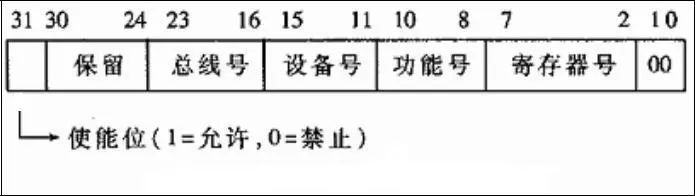
Figure 2, Composite Address Written to Address Register 0xCF8
Here, the bus number, device number, and function number are expansions of the configuration register address, which are the additional conditions mentioned above. First, each PCI bus has a bus number, with the primary bus numbered 0, while the others are assigned by the CPU during the enumeration phase each time a PCI bridge is detected, incrementally. The device number generally represents a PCI interface card (more precisely, a PCI bus interface chip), which usually depends on the position of the slot. Each PCI interface card can have several functional modules that share a PCI bus interface chip, including electronic circuits used for address mapping, to reduce costs.
Logically speaking, each “function” is essentially a device (those familiar with USB device drivers will find this very familiar, haha), so the device number and function number together can be referred to as the “logical device number”, and each card can accommodate a maximum of 8 devices.
Clearly, these fields (referring to the entire 32bit) combined together uniquely determine a PCI logical device in the system. Initially, only bus 0 can be accessed, and when scanning bus 0, if a device is found to be a PCI bridge, a new bus number, such as 1, will be assigned to it, allowing bus 1 to be accessed. This is one of the tasks of the enumeration phase.
Now, let the readers consider a question: when we take a PCI network card and insert it into the PC motherboard, what should we do first to write a driver for this network card? Readers can recall the previous content; since we said that the Linux kernel helps us with the enumeration and configuration of devices, shouldn’t I check the results of the enumeration work completed by the Linux kernel for this PCI network device before writing the driver? Or to put it more bluntly, I just inserted the network card; has the Linux kernel recognized this device? Note that recognizing a device is different from being able to use it, which is quite understandable.
Those who have installed PC network card drivers know that when the device driver is not installed, we can see this device in the device manager, but it shows a large yellow question mark. In Linux systems, we can check this using the lspci command.
Below is an excerpt from Chapter 3 of LDD3 regarding PCI drivers: the output of lspci (part of pciutils, which is included in most distributions) and the layout of information in /proc/pci and /proc/bus/pci. The sysfs representation of PCI devices also shows this addressing scheme, and when displaying hardware addresses, they can be shown as two values (an 8-bit bus number and an 8-bit device and function number), as three values (bus, device, and function), or as four values (domain, bus, device, and function); all values are often displayed in hexadecimal.
For example, /proc/bus/pci/devices uses a single 16-bit field (for ease of analysis and sorting), while /proc/bus/busnumber divides the address into three fields. The following content shows how these addresses are displayed, only showing the beginning of the output line:
$ lspci | cut -d: -f1-3

0000:00:00.0 Host bridge

0000:00:00.1 RAM memory

0000:00:00.2 RAM memory

0000:00:02.0 USB Controller

0000:00:04.0 Multimedia audio controller

0000:00:06.0 Bridge

0000:00:07.0 ISA bridge

0000:00:09.0 USB Controller

0000:00:09.1 USB Controller

0000:00:09.2 USB Controller

0000:00:0c.0 CardBus bridge

0000:00:0f.0 IDE interface

0000:00:10.0 Ethernet controller

0000:00:12.0 Network controller

0000:00:13.0 FireWire (IEEE 1394)

0000:00:14.0 VGA compatible controller
$ cat /proc/bus/pci/devices | cut -f1

0000

0001

0002

0010

0020

0030

0038

0048

0049

004a

0060

0078

0080

0090

0098

00a0
$ tree /sys/bus/pci/devices/

/sys/bus/pci/devices/

|-- 0000:00:00.0 -> ../../../devices/pci0000:00/0000:00:00.0

|-- 0000:00:00.1 -> ../../../devices/pci0000:00/0000:00:00.1

|-- 0000:00:00.2 -> ../../../devices/pci0000:00/0000:00:00.2

|-- 0000:00:02.0 -> ../../../devices/pci0000:00/0000:00:02.0

|-- 0000:00:04.0 -> ../../../devices/pci0000:00/0000:00:04.0

|-- 0000:00:06.0 -> ../../../devices/pci0000:00/0000:00:06.0

|-- 0000:00:07.0 -> ../../../devices/pci0000:00/0000:00:07.0

|-- 0000:00:09.0 -> ../../../devices/pci0000:00/0000:00:09.0

|-- 0000:00:09.1 -> ../../../devices/pci0000:00/0000:00:09.1

|-- 0000:00:09.2 -> ../../../devices/pci0000:00/0000:00:09.2

|-- 0000:00:0c.0 -> ../../../devices/pci0000:00/0000:00:0c.0

|-- 0000:00:0f.0 -> ../../../devices/pci0000:00/0000:00:0f.0

|-- 0000:00:10.0 -> ../../../devices/pci0000:00/0000:00:10.0

|-- 0000:00:12.0 -> ../../../devices/pci0000:00/0000:00:12.0

|-- 0000:00:13.0 -> ../../../devices/pci0000:00/0000:00:13.0

`-- 0000:00:14.0 -> ../../../devices/pci0000:00/0000:00:14.0
All three device lists are arranged in the same order, as lspci uses the /proc file as its information source. Taking the VGA video controller as an example, 0x00a0 means 0000:00:14.0 when divided into fields (16 bits), bus (8 bits), device (5 bits), and function (3 bits). Why does 0x00a0 correspond to 0000:00:14.0? This can be understood by looking at the content in Figure 2; based on the register in Figure 2, 0x00a0 represents the bus (8 bits), device (5 bits), and function (3 bits). 0x00a0=0000000010100000, which clearly shows that the high 8 bits are the bus number, which is 0. The remaining 0xa0=10100000 indicates that if the low 3 bits represent the function number, the remaining 10100 is the device number, and completing it to an 8-bit value gives 00010100, which is 0x14.
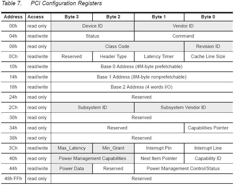
Figure 3, PCI Configuration Register Set
References:
[1] Analysis of Linux Kernel Source Code Scenario (Volume 2)
[2] Detailed Explanation of Linux Device Driver Development
[3] Linux Device Drivers (Third Edition)
[4] Kernel Documentation under pci.txt
[5] Mastering Linux Device Driver Development
[6] http://tldp.org/LDP/tlk/dd/pci.html
[7] http://linux.die.net/man/8/lspci
[8] http://www.ibm.com/developerworks/cn/linux/l-pci/
This article is about 20,000 words long, so it will be published in two parts, to be continued…
Previous article:Summary of Embedded Linux Technical Essentials
Promotional Message
Linux kernels above version 3.1 have supported device trees. If you are working on drivers or system-related work, it is recommended to learn about device trees; they will definitely be useful. We recommend the device tree video recorded by teacher Wei Dongshan over a period of three months, consisting of 6 lessons and 29 sections, lasting about 10 hours. The same content has been sold by peers for over 200, but we are offering it at a fair price of 69, welcome to inquire.
Highlights of the Device Tree Course:
1. Fair price, in-depth yet easy to understand, truly covering the device tree
2. Continuing the consistent style: teaching while drawing, coding on-site
3. Rich content, covering the handling of device trees by u-boot/kernel/driver
dts=>dtb=>device_node=>platform_device
Device Tree Course Directory:
Lesson 1: Introduction to Device Trees and Experience
Section 01: Three Ways to Write Character Device Driver Programs
Section 02: Traditional Way of Writing Character Device Driver Programs
Section 03: Compilation and Testing of Character Device Driver Programs
Section 04: Bus Device Driver Model
Section 05: How to Write Drivers When Using Device Trees?
Section 06: What to Do If You Want to Use It Without In-Depth Research?
Lesson 2: Specifications of Device Trees
Section 01: DTS Format
Section 02: DTB Format
Lesson 3: The Kernel’s Handling of Device Trees
Section 01: Simple Handling of dtb by Kernel head.S
Section 02: Handling of machine_desc in Device Trees
Section 03: Handling of Runtime Configuration Information in Device Trees
Section 04: Converting dtb to device_node
Section 05: Converting device_node to platform_device
Section 06: How does platform_device Match with platform_driver?
Section 07: Kernel Functions for Operating Device Trees
Section 08: Viewing Device Trees in the Root File System
Lesson 4: Support for Device Trees by u-boot
Section 01: Passing dtb to the Linux Kernel
Section 02: Principles of Modifying dtb
Section 03: fdt Porting
Lesson 5: Device Trees in the Interrupt System
Section 01: Introduction to Interrupt Concepts and Processing Flow
Section 02: Brief Overview of Linux Interrupt Handling Framework and Code Flow
Section 03: Evolution of Interrupt Numbers and irq_domain
Section 04: Experience Using Device Trees to Describe Interrupts on S3C2440
Section 05: Describing Interrupts in Device Trees
Lesson 6: Practical Operations
Section 01: Specifying Interrupts for DM9000 Network Card and Touch Screen Using Device Trees
Section 02: Simple Use of Clock in Device Trees
Section 03: Simple Use of Pinctrl in Device Trees
Section 04: Specifying Various Parameters for LCD Using Device Trees
Purchase Address:
https://item.taobao.com/item.htm?spm=a1z10.1-c-s.w5003-18996326770.1.764a82accZHBAf&id=577749510933&scene=taobao_shop
If you have concerns about the quality of the video, please watch two sections:
Traditional Writing of Character Device Drivers ▲
What to Do If You Want to Use Device Trees Without In-Depth Research? ▲
Below are some evaluations from students of the Device Tree course ▼

How to Get Selected Valuable Articles from This Public Account?
Please reply “m” in the public account backend to get it
Join the Community:
The official WeChat group of Wei Dongshan has been opened for students to communicate. Add the administrator’s WeChat (13266630429, verification: Join Group) to join, limited spots available on a first-come, first-served basis.