 What is Cable Redundancy
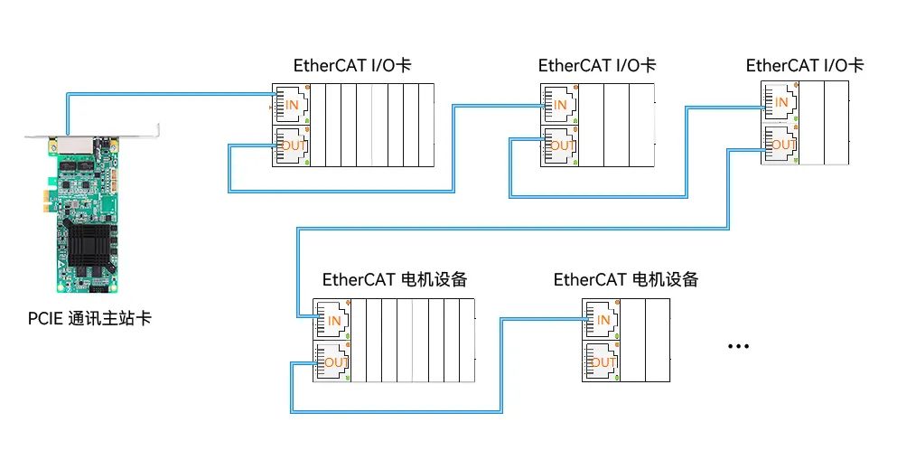
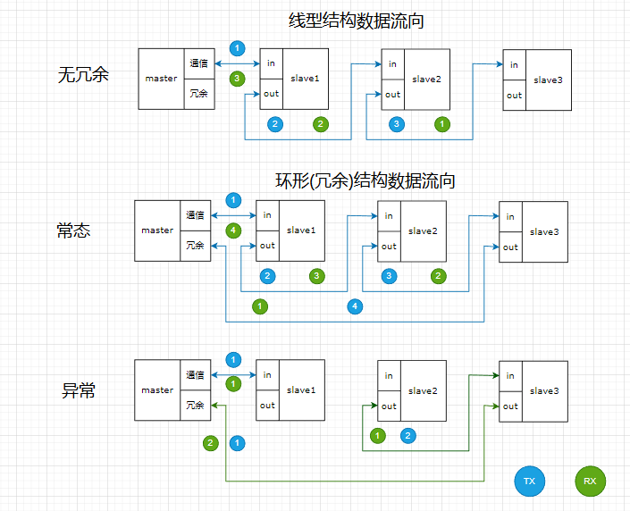
No matter what type of wiring method is used, a cable break will affect the normal operation of the equipment. Even traditional CAN, RS485, and other communication devices cannot operate normally. The problem needs to be solved: is there a standard solution that does not require too much additional design cost to address the aforementioned issues? Let’s take a look at the solution provided by the EtherCAT bus and the implementation principles of cable redundancy technology. First, let’s look at its connection method, as shown in Figure 3 below.
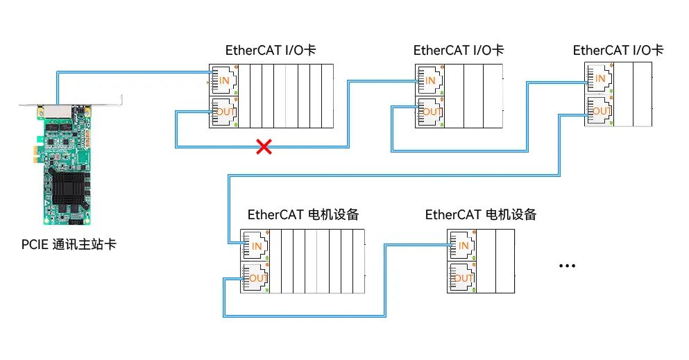
From the EtherCAT cable redundancy wiring diagram, it can be seen that the OUT terminal of the last slave device is reused to connect back to the master station, which is quite clever, right? It reduces hardware costs and solves the problem, and is indeed favored by everyone. Let’s take a closer look at its data flow. Suppose the cable between IO card 1 and 2 is still broken, its working principle is shown in Figure 4 below.
 Implementation of Redundant Master Station
EtherCAT slave devices in the link receive the Ethernet frame from the master station, copy their data from the Ethernet frame, write the current data, and forward the new Ethernet frame to the next slave device.
The master station, as the control end, actively requests data, and the slave responds. Therefore, the redundancy function is mainly implemented in the protocol stack on the master station side.
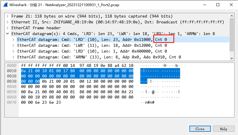
In the EtherCAT frame structure, each time data is input from the slave IN terminal, the slave increments the Cnt value by 1. In the data frame returned by the slave, the master station checks the Cnt value. If it differs from the configured value, it is deemed a network exception, and the specific location of the abnormal slave can be identified based on the Cnt. The EtherCAT frame is shown in Figure 5 below.
 Hardware Redundancy Technology
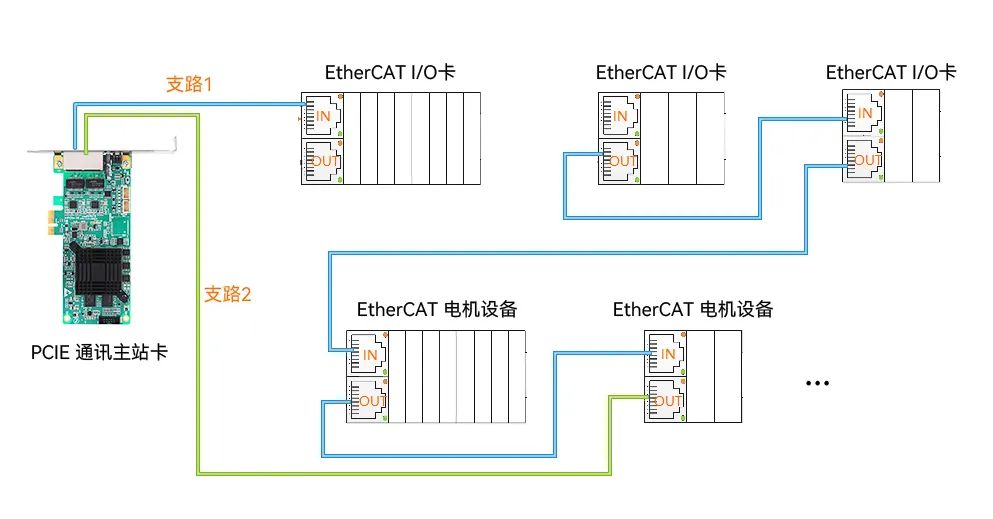
ZLG Zhiyuan Electronics PCIe EtherCAT communication card supports EtherCAT cable redundancy function, which can maintain communication between the master and slave devices even if the cable is physically interrupted at some point. At the same time, the redundancy function is designed using a hardware implementation scheme for quick response and lower packet loss rate, as shown in Figure 7 below.
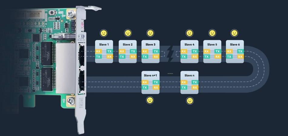
Figure 7 Hardware Redundancy Example
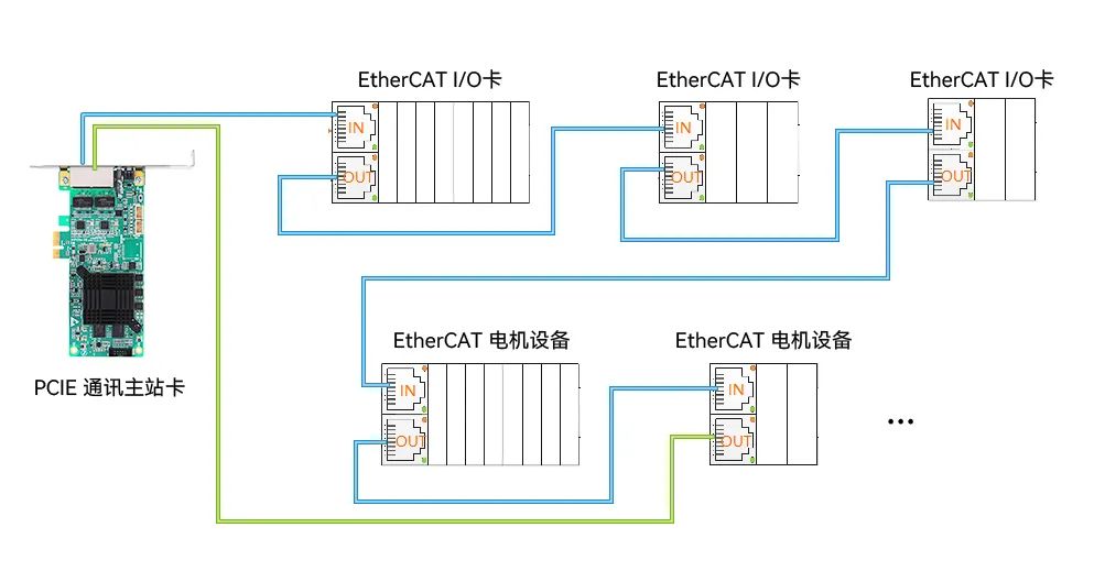
The PCIe EtherCAT communication card uses FPGA for Ethernet data transmission and reception, providing faster speeds. While the FPGA receives data, it also detects any break in the link with all slave devices. If a slave break is detected, the FPGA continues to send data from the redundant port without going through the protocol stack, still maintaining a complete link. The data flow direction is shown in Figure 8 below.
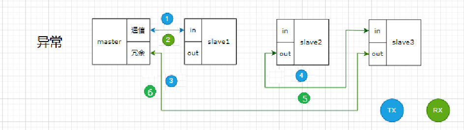
Figure 8 Hardware Redundancy Data Flow Direction
2. Hardware Redundancy Performance
The FPGA continues to send data from the redundant port without going through the protocol stack process, thereby increasing response speed and reducing data packet loss rate.
 The Role of Redundancy Technology and Product Applications
-
Cost-saving in Design EtherCAT cable redundancy uses the OUT port of the last slave device, allowing the redundancy function to be standardized.
-
Enhancing Reliability and Stability of Communication Systems In the industrial automation industry, it is usually required that devices on the bus operate continuously without stopping production. Redundancy technology can achieve reliability and stability in application systems.
-
Fault Diagnosis and Handling When a cable break occurs, the control continues to work with two links, and EtherCAT can automatically detect the fault point in the bus system, greatly simplifying system maintenance and improving device maintainability.
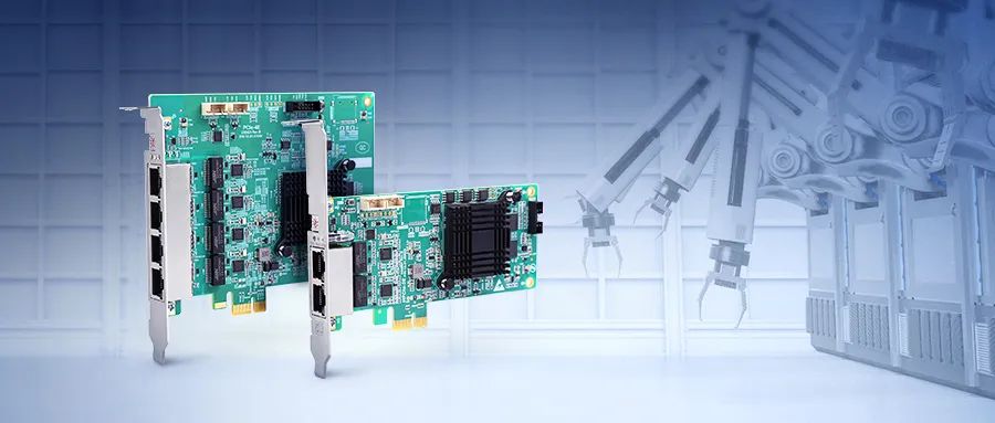
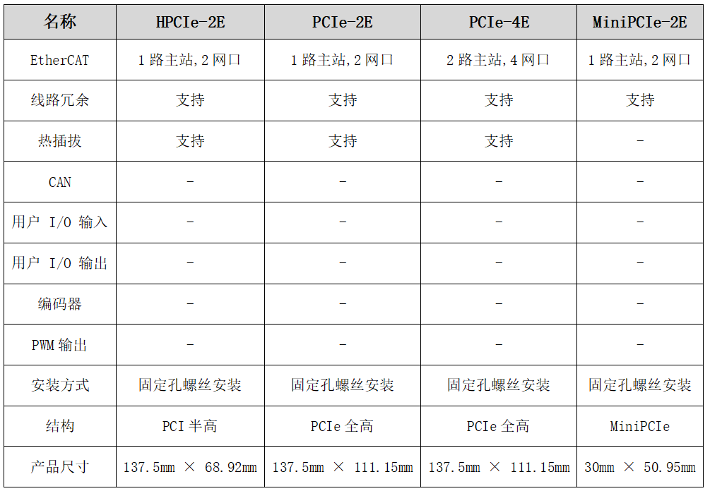
Zhiyuan Electronics PCIe EtherCAT Communication Card is a PCI-based EtherCAT bus communication interface card. It uses an advanced FPGA control scheme in the industrial field, achieving extremely high communication speeds and strong real-time performance. The PCIe EtherCAT communication card comes in MiniPCIE, half-card, and full-card designs, compatible with any type of 3.3 V/DC MiniPCIE and PCI slots. The EtherCAT communication card has the following advantages:
-
The PCIE communication card integrates a commercially licensed EtherCAT master station solution; -
Supports CoE, FOE, FSOE, hot-swappable slaves, master station hardware redundancy, and other functions; -
Minimum PDO cycle of 125μs, jitter of ±5μs; -
High-speed PCIe interface communication, supporting multiple operating system platforms; -
The PCIe interface offers higher efficiency in expandability and supports multiple platform operating systems.

For more articles, please click ” Read Original “