
Profibus is an important fieldbus widely used in industrial control.
This article analyzes the common problems that occur in Profibus networks, discusses their causes, provides several diagnostic methods, compares the advantages and disadvantages of these methods, and summarizes interference prevention and handling measures.
Since the 1990s, the rapid development of 4C technology in the information industry (Computer, Control, Communication, CRT) has led to an expansion of control range and scale in the industrial control field, an increase in performance, information volume, and real-time requirements, as well as a combination of control, management, and decision-making. Fieldbus technology emerged as a result, and it can be said that fieldbus is an inevitable product of automation development.
A fieldbus refers to a data bus that facilitates digital, serial, and multi-point information exchange between field devices installed in the process control area and the central control system in the control area. The bus protocol is the core of the fieldbus; it is systematic, has complete hardware and software support, and can form systems and products. The standardization of bus protocols is a prerequisite for achieving openness and interoperability. Fieldbus follows a unified bus protocol, enabling bidirectional digital communication, featuring various intelligent functions, enhancing information processing and control capabilities at the field level, and providing rich status, diagnostics, and parameter information. Fieldbus technology supports the continuous development of control systems from traditional distributed control systems (DCS) to modern fieldbus control systems (FCS).

Profibus Fieldbus
In the development of fieldbus technology, Profibus fieldbus technology is undoubtedly the most widely used, primarily led by international organizations composed of German and European companies. The Profibus bus protocol communication model refers to the ISO-OSI standard for the seven-layer reference model of information communication and adds a user layer oriented towards users. As shown in Figure 1, Profibus-DP simplifies it to three layers, defining only the first layer (physical layer), second layer (data link layer), and user layer.
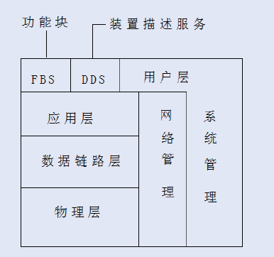
Figure 1 Simplification of Profibus for OSI Model
Profibus is a fieldbus technology used for data communication and control at the workshop level of factory automation, enabling decentralized digital control and field communication networks from field device levels to workshop-level monitoring, thus providing a feasible solution for achieving comprehensive factory automation and intelligent field devices. Profibus features long transmission distances, high speed, high data security, simple installation, and ease of debugging. It is widely applicable in manufacturing automation, process industry automation, and other fields such as building automation, transportation, and power. Profibus is divided into three different series according to application scenarios: Profibus-DP, Profibus-PA, and Profibus-FMS. The FMS protocol layer is relatively complex and cannot meet the current high-speed transmission requirements of fieldbus, gradually phasing out of practical applications, while the most commonly used series are DP and PA.

Faults and Their Cause Analysis
During the construction and use of Profibus bus networks, especially during installation debugging and operation of fieldbus control systems, various issues such as installation configuration or electromagnetic interference can cause Profibus networks to be interrupted, communication performance to decline, network instability, and site loss. Based on extensive practical experience, faults can generally be divided into physical faults and network logic faults. Most faults are physical faults, primarily due to non-standard installations, cable layout, and interface issues, along with some complex transient faults occurring frequently.
Physical faults mainly include the following:
1. Faults caused by lines and network plugs;
2. Faults caused by severe voltage and current fluctuations, noise interference (common-mode and differential-mode interference), and electromagnetic interference;
3. Faults caused by communication ports and modules;
4. Faults caused by middleware and couplers. Network logic faults primarily include: ① Hardware configuration faults such as baud rate configuration, site module configuration issues; ② Communication faults, functional block configuration issues, improper selection of functional blocks during programming, and some signals requiring delay processing.
Here, we mainly study the most common physical faults.
Firstly, identifying the factors causing interference is crucial for taking measures and addressing the issues directly. From a hardware perspective, in projects with numerous electrical devices, the complexity of electrical wiring, multiple control devices, and complicated control circuits can easily lead to mutual influence among various lines. Improper cable layout in bridge racks, non-compliant grounding, inadequate shielding where shielding is required, and placing communication lines close to high-power and high-current devices can easily lead to faults in the Profibus network.

Diagnostic Methods
With the development of fieldbus technology, the types of bus faults have also increased, and these issues are often not easy to locate. To adapt to these practical problems, various diagnostic methods have emerged over time. These methods mainly include:
1. Using simple tools such as site status indicators and multimeters for troubleshooting: This method can only simply check whether the Profibus cable is connected, whether all sites are connected, and whether the terminal resistors at both ends are connected, etc. This method is only used for preliminary checks.
2. Programming software, such as Siemens Step7 software and ABB Control Builder programming software, can clearly display the entire network topology and information of each site. Comprehensive network status information can be obtained, facilitating fault location. This is useful for overall fault detection but may not provide high accuracy for signal quality diagnostics. Figure 2 shows the site display of the programming software.
3. Diagnostic repeaters and handheld diagnostic devices: For instance, Siemens diagnostic repeaters and diagnostic device BT200 have more detailed detection functions for the entire bus network, accurately checking for reverse connections, short circuits, and recording fault time, causes, network topology, and error locations. However, this type of detection has limitations; for instance, BT200 is primarily used during the bus wiring phase, and diagnosing while the device is in operation can be quite challenging. The length of the diagnostic repeater should be within 100m, and network configuration is required, placing demands on the network.
4. Some packet capture software, such as Amprolyzer, is dedicated to diagnosing lower-level data and serves as software for assessing communication quality. Its diagnostic functionality is relatively singular, focusing only on communication quality without cable fault localization capabilities.
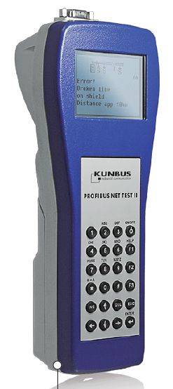
5. Comprehensive diagnostic tools, such as Germany’s Comsoft NetTEST II and Softing’s PBT-5 devices. These devices can systematically test Profibus networks, accurately locating most common errors. Such comprehensive diagnostic tools are equipped with oscilloscope functions to clearly detect the communication quality of transmission signals and can be used conveniently during both device operation and debugging stages without requiring configuration, allowing for data recording and report generation. When combined with permanent detection tools, they can provide continuous monitoring of the network, maximizing the reduction of factory downtime for users. The NetTEST II diagnostic instrument is shown in Figure 2.
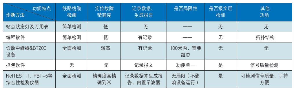
By comparing various diagnostic methods, it can be seen that the applicability and detection functionalities of these methods vary. As comprehensive diagnostic tools, they offer complete functionalities but are relatively more expensive. However, they can effectively troubleshoot Profibus network faults on-site, ensuring normal production needs. Factories with the conditions can choose comprehensive diagnostic tools to enhance enterprise efficiency. Table 1 compares several diagnostic methods, showing that comprehensive diagnostic tools have more extensive and powerful functionalities.
Table 1 Comparison of Several Diagnostic Methods

Interference Handling
In engineering projects, various types of interference should be comprehensively addressed based on the actual site conditions. First, proper cable routing and shielding should be done; control cables and various signal lines must be well shielded, and control cables should be placed separately. The Profibus-DP bus twisted pair should avoid running alongside other signal lines, control cables, and high-voltage power cables in the same conduit to minimize interference sources. During wiring, the shielding layer should be properly connected, leaving an appropriate length of shielding layer to avoid contact with internal wires.
Secondly, good grounding is an important measure for preventing interference in fieldbus systems. The “ground” is generally selected as the reference point of zero potential, and grounding establishes a pathway between two contact nodes, connecting electrical devices to the “ground.” The primary purpose of grounding is to protect the safety of people and equipment and to reduce electromagnetic interference. Ensuring the stability of communication interfaces is also very important. In addition to grounding, the impact of other device power supplies and cables on communication signals is significant. When conditions allow, devices and power supplies with good isolation performance should be selected, and wiring should be as isolated as possible. Furthermore, to combat interference, a large number of analog signal isolators (also known as signal transmitters) should be used to resist interference. Signal isolators provide three-way isolation for various analog signals, including power, input, and output, while conditioning the signals to significantly reduce interference. Due to their strong anti-interference capabilities, the installation of signal isolators has become a common practice in automation control systems, and they are widely used on-site.
The Profibus bus network has become a very important fieldbus standard due to its numerous advantages and has been widely applied. However, various network faults arise during installation debugging and on-site operation. Some faults are quite complex and difficult to troubleshoot. Appropriate diagnostic methods and tools should be selected based on the characteristics of the faults to analyze and diagnose quickly, accurately locate the faults, and handle them promptly, reducing debugging time and minimizing downtime, thereby increasing factory efficiency.

– End –
This article is from CONTROL ENGINEERING China January-February 2019 issue, in the “Technical Articles” section, originally titled: Analysis of Profibus Bus Diagnostic Methods and Interference Handling Measures.

Cover of this issue

To read each issue of the magazine for free, please check the CONTROL ENGINEERING China WeChat subscription account’s custom menu.