 Plug-in Module
To meet the control needs of personalized large systems, Zhiyuan Electronics has launched a plug-in motor drive module. This system uses the EtherCAT bus, with a slave module size of 59mm*50mm, and employs a 40-pin standard header interface. Users can create distribution baseboards as needed, and slave boards are plugged into the baseboard to cascade through the EtherCAT network, supporting a maximum of 255 nodes.
-
Adapting to changes with minimal effort, create distribution baseboards as needed to accommodate the ever-changing wiring requirements. -
Small size, large system, integrating the maximum number of slaves within the smallest volume to achieve control of large systems. -
High precision and fast layout, based on EtherCAT, achieving high precision distributed control and plug-and-play rapid layout.
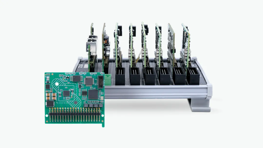
Figure 1: Plug-in Motor Drive Module
Stepper Motor Drive Module
-
24V~48V/1.5A~3A two-phase stepper motor; -
1/2/4/8/16/32/64/128/256 microstepping options; -
CiA402 motion control protocol, supporting CSP/PP/HM/PV modes; -
3 digital inputs, 1 set of ABZ quadrature encoding input; -
Open-loop or encoder closed-loop control options.
-
Digital input, 24V level, 3ms debounce, 16 channels, high and low level selectable;
-
Digital output, 24V level, single channel 0.5A, 16 channels, high and low level selectable;
-
Analog input, 12-bit, 8 channels, current type/voltage type selectable;
-
Analog output, 12-bit, 8 channels, voltage type.
Power Module
-
24VDC input, 3.3VDC/2.5A output.
 Usage of the Power Module
The plug-in motor drive module can connect multiple slave modules to easily achieve synchronized control of hundreds of motor drives. However, such a large number of modules places high demands on the 3.3V power supply used for EtherCAT communication; on one hand, the power must be sufficiently large (around 250mA/module), and on the other hand, ripple and other interference must be minimized. The accompanying power module ZPWB-240302 is specifically designed to provide efficient and stable power for EtherCAT communication.
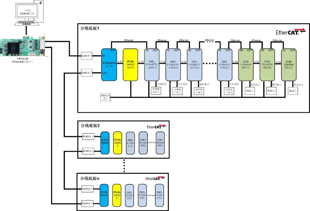
Figure 2: Distribution Baseboard
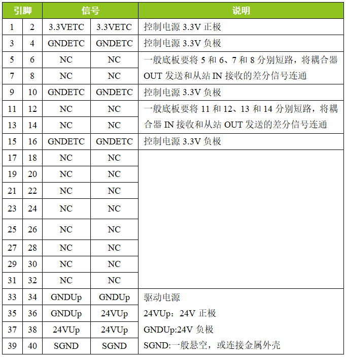
 Power Module Interface Description
Table 1: Pin Definition Description
 Classic Wiring Diagram of Power Module
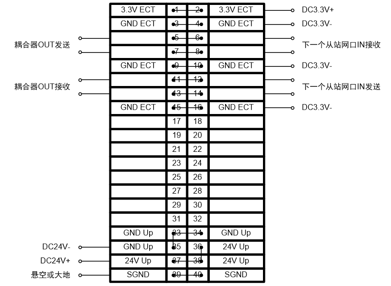
The above figure shows the pin definitions and connection methods of the power module. Below is the selection table for various modules.
Table 2: Motor Module Selection Table
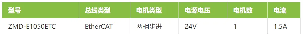
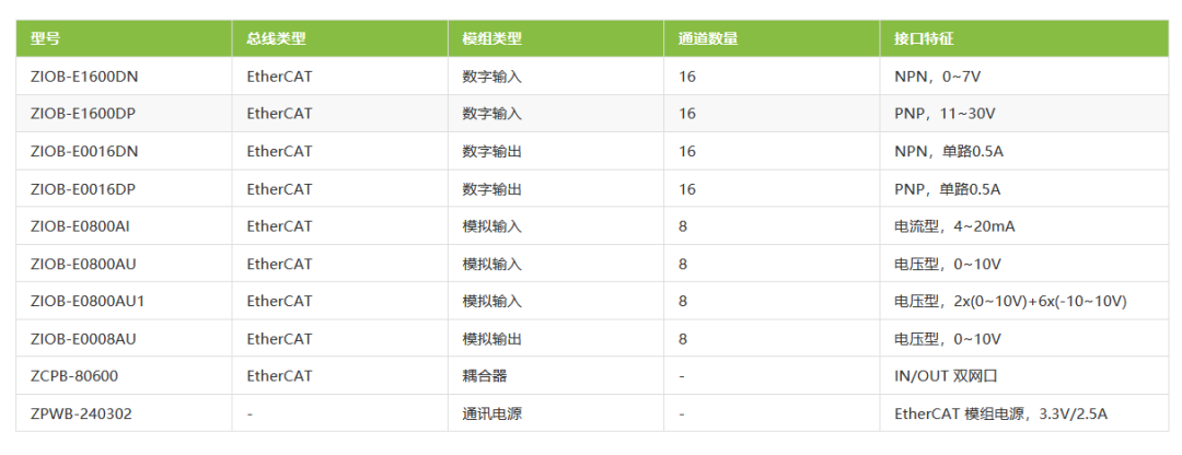
Table 3: I/O Module Selection Table
https://manual.zlg.cn/web/#/333/13047

EtherCAT Series Articles
[New Product Launch] ZMC900E Domestic High-Performance EtherCAT Bus Controller
[New Product Launch] ZLG Zhiyuan Electronics PCIe EtherCAT Communication Card Officially Released!
[200 Motor Drives] How to Run in Sync? — Flexible Motor Drive System Based on EtherCAT
[200 Motor Drives] How to Quickly Build a Flexible Automated Production Line?
[Pin Machine PLC Development] Developing Motion Logic with AWBlock
[Pin Machine HMI Development] Developing Human-Machine Interface with AWTK
[Technical Sharing] Introduction to EtherCAT Data Frame Format and Addressing Methods
[Technical Sharing] “Transformation” — Motion Control of Pin Machines
[Technical Sharing] How to Upgrade Slave Firmware via EtherCAT Bus?
[Technical Sharing] How to Remedy Communication Cable Disconnection with EtherCAT Redundancy Technology?
[Technical Sharing] How to Accurately Analyze Motion Data of Humanoid Robots?
[Technical Sharing] Why is EtherCAT So Popular in Motion Control Buses?
[Product Application] ZMC900E Controller ROS2 Environment Installation Guide
[Product Application] Real-time Testing of EtherCAT Master Controller System
[Product Application] ZMC900E Domestic EtherCAT Master Controller — Power Port Conducted Disturbance Rectification
[Product Application] ZMC300E EtherCAT Master Controller Achieving Complex Motion Trajectory Planning Principles and Applications
[Product Application] Step-by-Step Guide to Using ZMC300E for Drawing
[Product Application] Three Steps to Get Your EtherCAT Motors Running
[Product Application] How EtherCAT Ensures Efficient, Real-time, and Flexible Fieldbus Communication
[Product Introduction] ZMC601E Bus-type Edge Controller — Leading the Digital Transformation of Manufacturing Enterprises
[Product Introduction] ZMC600E EtherCAT Master Controller Newly Launched
[Product Introduction] ZLG Launches Next Generation Industrial Robot Solutions to Inject New Vitality into Industrial Robots
For more past articles, please click ” Read Original “.