As we all know, the TwinCAT development environment’s EtherCAT | Online interface can diagnose most EtherCAT issues, such as checking the OP status of the master and each slave, CRC error count, etc. Below are several “hidden” tools in TwinCAT.
The above content is included in three documents, highly recommended to download from the Beckhoff Virtual Academy “https://tr.beckhoff.com.cn”, worth detailed study:
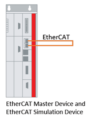
1 EtherCAT Simulation Tool
This tool is originally designed for hardware-in-the-loop debugging with TwinCAT Matlab/Simulink, and can also be used with specialized automation simulation software and TwinCAT‘s IO interfaces. I found another use for it: practicing EtherCAT fault diagnosis—because engineers are not always in the workshop, when it comes to discussing how to handle an EtherCAT fault, it’s impossible to practice without hardware on hand. Beckhoff engineers have relatively good experimental conditions to test on a Demo rack, but if the system is complex and there are many IO stations, it is still very difficult to reproduce faults.
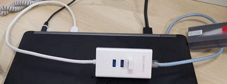
The simplest EtherCAT simulation environment is as follows:
For example, when testing on a programming notebook, by extending a USB to Ethernet converter, the computer has two independent wired network cards, and connecting them with a network cable creates the hardware platform for the above test:
The configuration of EtherCAT Simulation is also very simple:
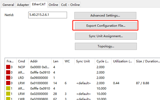
(1) Export EtherCAT Configuration File

After configuring the EtherCAT network either from the project file or manually, set the adapter to use, and then export the EtherCAT configuration file:
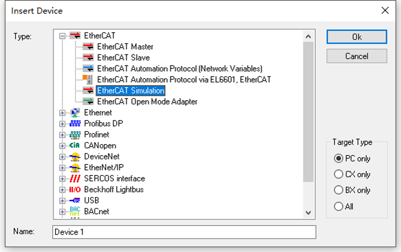
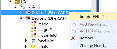
(2) Manually Add EtherCAT Simulation
(3) Import Configuration File to Simulation
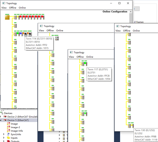
(4) Activate Configuration to See Results
If the Adapter is selected correctly, the EtherCAT driver is installed correctly, and the dual network cards are interconnected, all slaves and their statuses can be displayed in the EtherCAT Master‘s Topology window. To test the simulation effect of a large EtherCAT network, this example is configured with 100 EK1100 and several XFC modules, compact drive modules, etc.:
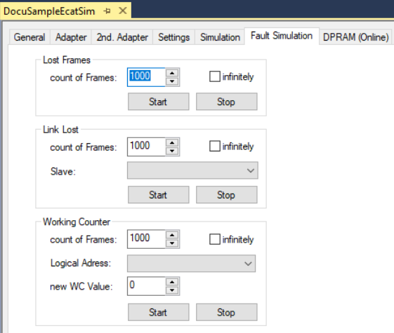
EtherCAT Simulation can simulate packet loss, disconnection, WC and other faults, simulating both transient and permanent faults:
This function requires TE1111 authorization, and the trial version can only run for 30 minutes. When Beckhoff engineers practice EtherCAT diagnostics using EtherCAT Simulation, they can borrow a USB Dongle with complete authorization, while Beckhoff users need to purchase it.
The simulation effect is related to CPU performance; the smaller the jitter and the shorter the cycle, the better the simulation effect.
For simulating slaves with DC clocks, such as servo drives, XFC modules, etc., only the EtherCAT interface can be simulated, and the internal functions of the module itself cannot be simulated. Due to hardware limitations, the DC characteristics simulated are not as good as those of real physical slave devices.
The typical use of EtherCAT Simulation should be combined with simulation software to simulate field devices to assist in virtual debugging of EtherCAT master applications. Fault simulation can be triggered from TwinCAT XAE or from the simulation software. The triggering from XAE in this example is merely for demonstration convenience.
For complete functionality, please refer to:
2 EtherCAT Slave Registers
Most of the time, through the TwinCAT XAE EtherCAT Online interface, Slave Diagnose interface, and TwinCAT Alarm form, you can visually diagnose slave information. So where does this information come from? It must come from the slave’s Registers, collected by the master and presented in a visual manner in TwinCAT XAE. Ordinary users only need to use these visual interfaces. However, if you want to understand the underlying mechanisms, TwinCAT also provides a channel for direct access to these Registers. On the slave’s Advanced Setting page, select the last item “ESCAccess/Memory“:
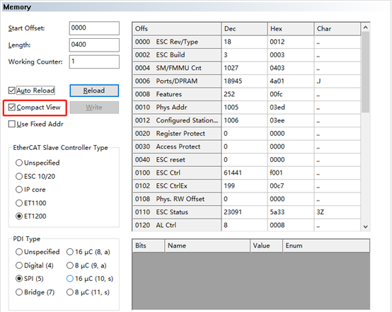
Input Start Offset and Length, you can define the starting address and length of the displayed data. So what commonly used information is located at what addresses?
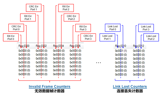
(1) Connection Loss Counter
|
Register Memory Address |
|
|
|
|
|
|
|
|
|
|
|
|
|
|
|
|
|
|
(2) Invalid Frame Counter
|
|
|
|
|
|
|
|
|
|
|
|
|
|
|
|
|
|
|
|
|
|
|
|
|
|
|
|
|
|
|
|
|
|
|
|
(3) EtherCAT Online Interface Displays CRC
In TwinCAT, the EtherCAT master’s Online page always displays count values in a word-oriented manner. However, the default Online interface does not display the above counts, which need to be set in the master’s Advanced Setting page’s Online View:
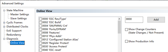
After checking 0300 and other Registers, they can be displayed in Online:
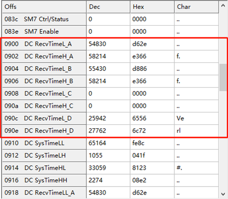
(4) Frame Arrival Timing at Slave Ports
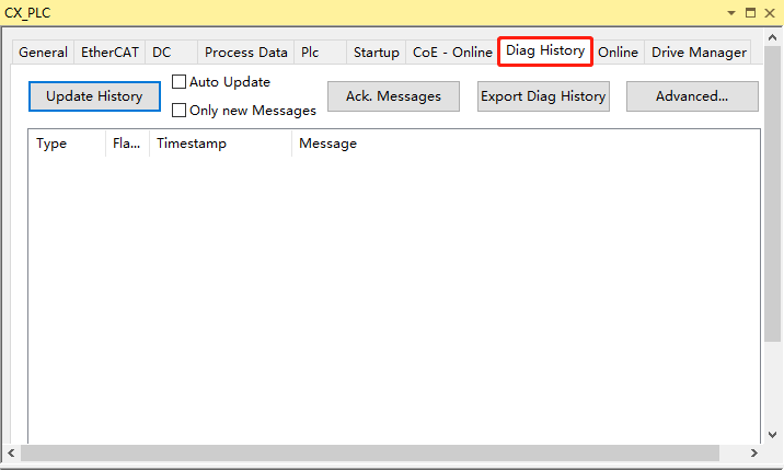
(5) Historical Diagnostic Information Register 0x10F3
(6) AL Status Code Register 0x0134
Configuration Errors:
Runtime Errors:
3 Frame Timing Analysis
For ordinary IO modules or EtherCAT slaves, it does not matter if the EtherCAT Frame arrives early, late, or even occasionally misses, but for EL modules or EtherCAT slaves with a DC clock and enabled DC function, late or missing frames will trigger alarms.
So, when does the Frame actually arrive at a specific EtherCAT slave? TwinCAT XAE provides a visual interface. Taking an EtherCAT network containing two DC slaves EL7201 and EL7211 as an example, while the controller is in Runing mode, open the Slave Diagnose window from the EtherCAT Master‘s Advanced Setting interface:
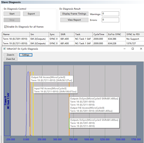
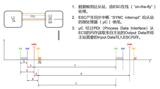
Here are a few terms to explain:
The timing points represented by these terms have the following relationships on the slave side:
Try modifying the Shift Time of the master and slave, and then display the timing diagram in this visual interface to gain a deeper understanding of EtherCAT distributed clocks. When the slave reports Sync Lost, you can go to this interface to further observe fault information. For detailed instructions, please refer to:3_EtherCAT Synchronization -cn V2.pptx (Page48-60)
4 EtherCAT Frame Jitter
The ideal situation is that each task cycle’s EtherCAT Frame starts at the same time, but in reality, due to the jitter of the TwinCAT real-time kernel and fluctuations in task computation, the actual start time of the Frame always deviates from the theoretical value, including positive (pos) and negative (neg) deviations. TwinCAT XAE provides the DistributedClocks Diagnosis function in the EtherCAT master’s Advanced Setting to monitor the actual fluctuation:
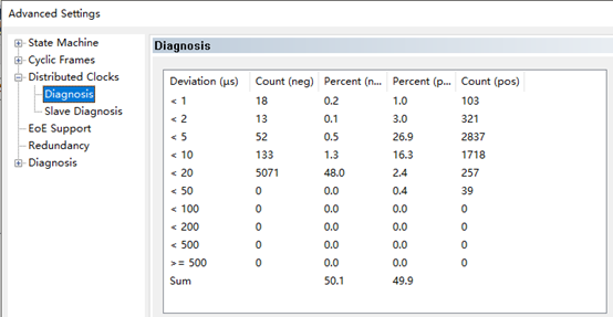
The above figure shows that the maximum deviation is between 20-50us, calculated at 50us. If this deviation exceeds 20-30% of the task cycle, it is easy to cause synchronization errors. Therefore, the shorter the task cycle—such as less than 1ms—the greater the probability of synchronization errors. If the maximum deviation exceeds 500us, it is no longer a problem with the synchronization task, but rather a need to check the EtherCAT network card, driver, or TwinCAT real-time kernel. For example, testing and running TwinCAT on a third-party PC often leads to excessive jitter issues, which may affect microsecond-level tasks that require distributed clocks.
5 Complete AL Status Code Explanation
|
|
No error No error |
|
0x0001 |
Unspecified error General Error which is not defined in the following list |
|
0x0002 |
No Memory Local Application runs out of memory (e.g. dynamic memory allocation for emergency messages |
|
0x0011 |
Invalid requested state change Requested state change is invalid(e.g. IS, IO, PO, PB, SB, OB) |
|
0x0012 |
Unknown requested state Requested state change is unknown(e.g. if the requested state code is not 1, 2, 3 4, 8) |
|
0x0014 |
No valid firmware The downloaded file is no valid firmware file |
|
0x0013 |
Bootstrap not supported The device doesn’t support Bootstrap state |
|
0x0015 |
Invalid mailbox configuration The mailbox SyncManager configuration is not valid in Bootstrap state |
|
0x0016 |
Invalid mailbox configuration The mailbox SyncManager configuration is not valid in PREOP state |
|
0x0017 |
Invalid sync manager configuration Sync manager configuration is not valid |
|
0x0018 |
No valid inputs available Slave application cannot provide valid inputs |
|
0x0019 |
Slave application cannot receive valid outputs |
|
0x001A |
Synchronization error Multiple synchronization errors. Device is not synchronized anymore (should be used if no specific Synchronization error can be distinguished) |
|
0x001B |
Sync manager watchdog No process data received yet (s->O) or not received within a specified timeout value |
|
0x001C |
Invalid Sync Manager Types |
|
0x001D |
Invalid output Configuration SyncManager configuration for output process data is invalid |
|
0x001E |
Invalid Input configuration SyncManager configuration for input process data is invalid |
|
0x001F |
Invalid watchdog configuration watchdog Settings are invalid (e.g. SyncManager watchdog trigger is enabled but no watchdog timeout is defined) |
|
0x0020 |
Slave needs cold start Device requires a power off-power on reset |
|
0x0021 |
Slave needs INIT Application requests INIT state |
|
0x0022 |
Slave needs PREOP Slave application requests PREOP state |
|
0x0023 |
Slave needs SAFEOP Slave application requests SAFEOP state |
|
0x0024 |
Invalid Input Mapping Input process data mapping does not match expected mapping |
|
0x0025 |
Invalid Output Mapping Output process data mapping does not match expected mapping |
|
0x0026 |
Inconsistent Settings General settings mismatch |
|
0x0027 |
Freerun not supported |
|
0x0028 |
Synchronization not supported |
|
0x0029 |
Freerun needs 3 Buffer Mode FreeRun Mode, sync manager has to run in 3-Buffer Mode |
|
0x002A |
Background Watchdog |
|
0x002B |
No Valid Inputs and Outputs |
|
0x002C |
Fatal Sync Error Fatal Sync Error Sync or Sync1 are not received anymore |
|
0x002D |
No Sync Error Sync not received: In SAFEOP the slave waits for the first Sync or Sync1 events before switching to OP if these events were not received during the SAFEOP to OP-Timeout time the code should refuse the state transition to OP with this AL status (System Time offset too big, no DC event received) |
|
0x0030 |
Invalid DC SYNC Configuration Distributed Clocks configuration is invalid due to application requirements |
|
0x0031 |
Invalid DC Latch Configuration DC Latch configuration is invalid due to application requirements |
|
0x0032 |
PLL Error Master not synchronized at least one DC event received |
|
0x0033 |
DC Sync IO Error Multiple synchronization errors. IO is not synchronized anymore |
|
0x0034 |
DC Sync Timeout Error Multiple synchronization errors. Too many SM Events missed |
|
0x0035 |
DC Invalid Sync Cycle Time |
|
0x0036 |
DC Sync Cycle Time DC Sync Cycle time does not fit application requirements |
|
0x0037 |
DC Sync1 Cycle Time DC Sync1 cycle time does not fit application requirements |
|
0x0041 |
MBX_AOE |
|
0x0042 |
MBX_EOE |
|
0x0043 |
MBX_COE |
|
0x0044 |
MBX_FOE |
|
0×0045 |
MBX_SOE |
|
0x004F |
MBX_VOE |
|
0x0050 |
EEPROM No Access EEPROM not assigned to PDI |
|
0x0051 |
EEPROM Error EEPROM access error |
|
0x0060 |
Slave Restarted Locally |
|
0x0061 |
Device identification value updated The device identification value was updated and is now valid |
|
0x00F0 |
Application Controller available The local application releases the application controller which is now available and services the EtherCAT state machine and all other device features This optional AL Status Code shall only be used for devices that have a different power supply for the ESC and the application controller and which cannot define a maximum timeout value for transition to OP NOTE: Use case can be if ESC is powered before application controller. Err Indication can be used by Master to indicate that slave is ready for boot-up (instead of checking polling) |