In practice, we summarize and share discussions in our circle, making the most grounded public account.
Beckhoff users extensively use EtherCAT, and generally do not need to have a deep understanding of EtherCAT because most projects only require automatic scanning and default settings. However, when communication errors occur and troubleshooting is needed, engineers must understand some EtherCAT basics and learn how to optimize configurations.
This article aims to introduce the TwinCAT built-in EtherCAT diagnostic functions and several common optimization measures in a simple way.
The diagnostic functions include:
EtherCAT Online interface diagnosing network hardware errors
EtherCAT Topology page to view graphical EtherCAT status
Adapter page to view Ebus current
PLC diagnosing EtherCAT status program code
The optimization measures include:
Sync Unit settings
Disabling WcState of servo drives
Checking EtherCAT network grounding
Modifying slave Shift Time
Hot Connect settings
Layout principles of EL modules
The technical documents from ETG and Beckhoff regarding EtherCAT diagnosis and principles are more detailed and complete. Interested users can download:
《EtherCAT Basic Principles》
《EtherCAT Diagnosis》
《EtherCAT Synchronization》
1 EtherCAT Diagnostic Functions
The simplest EtherCAT diagnostic tool is TwinCAT, where the most commonly used diagnostic interfaces are: EtherCAT Online interface, EtherCAT Topology interface, and Adapter interface, which will be introduced below.
1.1 Online interface diagnosing network hardware errors
The most commonly used functions on this interface are:
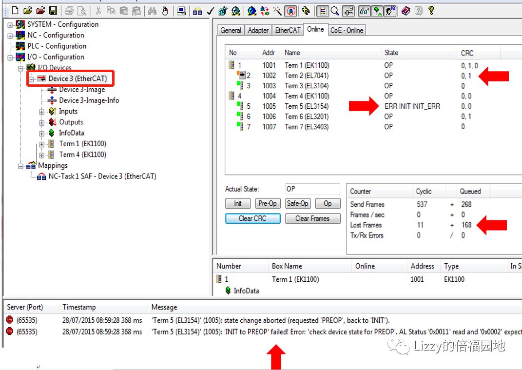
Viewing and switching the status of the master and slave stations, checking the Lost Frame status of the master station.
Viewing the status of all slave stations and the CRC check status of each port
Viewing the state change count of each slave
Viewing the state machine errors of the slaves
If both the master and slave stations are in OP state on this interface, while some slave signals are still abnormal and the software reports an error, it is very likely due to WcState reporting invalid data. Please refer to the next section: Sync Unit usage
The monitoring of the master station status is already very intuitive and does not need explanation. The following only explains the last three situations:
1.1.1 Viewing slave station status and port CRC check status
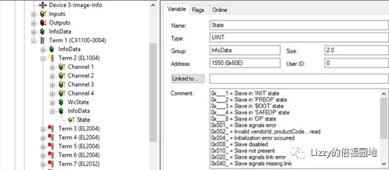
When the slave status is OP and the CRC check value is 0, it is a normal state. If a certain slave status is not OP, it is necessary to locate the InfoData|State of that slave, as shown in the figure:
On the Variable page, the meanings of the Word values of the state can be displayed, and switching to its Online page can show the current value of the Word.
The CRC value is related to the module type, all EL modules only have two Ports. The left value of the CRC check indicates the interface status with the previous module, while the right CRC value indicates the interface status with the next module.
1.1.2 Slave state change count
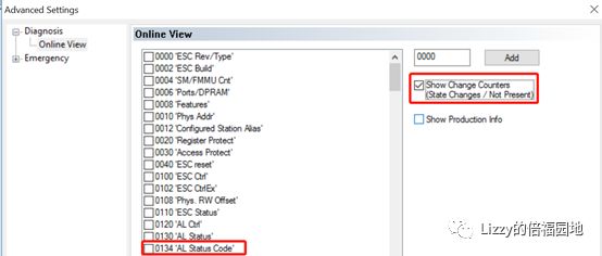
Checking the slave state change count is to track the situation where individual slave states have errors and then automatically recover. Because after the state recovery, it shows normal on the Online interface, but the error moment may not be monitored by humans:

If the change count of some modules is significantly higher than that of other modules, then the probability of that module having errors is higher.
1.1.3 State machine errors
 In the previous step’s window, check the 0134 “AL Status Code” to view the error codes:
– 0x0003 : Invalid Device Setup (The configuration order of KL modules on BK1xxx is incorrect)
– 0x001D : Invalid OutputConfiguration (The configured output process data is invalid)
– 0x001E : Invalid Input Configuration(The configured input process data is invalid)
– 0x0035 : Invalid Sync Cycle Time (The CycleTime set in DC mode is not supported)
– 0x001A : Synchronization error (Network jitter causes the loss of synchronization of slaves)
– 0x001B : Sync manager watchdog (The slave has not received periodic data for a time that exceeds the watchdog time)
– 0x002C : Fatal SYNC error (ESC no longer receivesSYNC hardware interrupt)
If it is another value, refer to the ETG official manual for the definition of AL StatusCode.
1.2 EtherCAT Topology interface
In the master station’s EtherCAT | Topology window, you can view the EtherCAT network topology diagram online or offline:
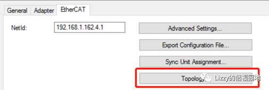
If the previous Online page is text-based, this is the graphical version of the Online page. When hovering over a module, the module’s name can be displayed. When displayed online, the mark above each slave indicates the CRC status, and if they are all green, it is normal.
1.3 Adapter page, viewing available Ebus current
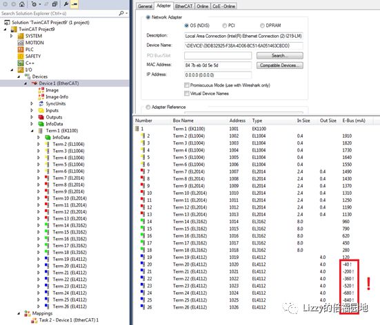
Based on experience, the available Ebus current should not be used up to 0, but should retain about 300mA margin. For example, in the above figure, before the first EL4112, an Ebus power module EL9410 should be added.
1.4 PLC diagnosing EtherCAT status demo program
For specific implementation methods, see the document:
Http://www.baclizzy.com.cn/20180422EtherCAT optimization settings/
2 Sync Unit and WcState
2.1 Sync Unit principle
TwinCAT configures EtherCAT master stations according to Task configurations. For example, if the PLC Task0 cycle is 10ms, there is a corresponding sending cycle of 10ms for the Frame. If the NC cycle is 2ms, there is a corresponding sending cycle of 2ms for the Frame. Each Task enters the Output phase after the calculation phase ends, sending the corresponding Frame.
Each Frame refreshes the IO data of the slaves through three commands: LRW (read and write), LWR (write), LRD (read). The commands (Cmd) that refresh which slaves’ data determine the theoretical value of the Working Counter (WC). As shown in the figure:
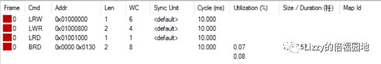
According to the master’s configuration, each Frame includes several SyncUnits, each SyncUnit includes several Slaves. After the Frame successfully passes through the slaves and reads and writes, the Cmd of the corresponding SyncUnit increases its Working Counter accordingly. When the Frame returns to the master after passing through all slaves, the master can determine whether all Slaves of this Cmd operation were successful based on whether the actual WorkingCounter of each SyncUnit matches the theoretical value. If not successful, the WcState status of all Slaves involved in this Cmd operation will be True, indicating Data Invalid (invalid data).
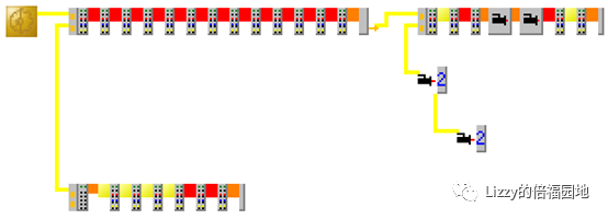
Assuming the PLC task needs to control all IO modules in the diagram below, it needs to use the LRD command to refresh all EL1004 data, and the accumulation process of the Working Counter is as follows:
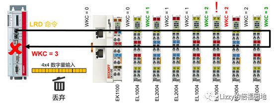
In the above figure, the red ! marked EL1004 failed to exchange data successfully, so the Frame passed through 4 EL1004 modules, but the returned WKC is 3. The master station determines that this data is invalid, and TwinCAT will discard this data, meaning that the data from these 4 EL1004 modules were not refreshed during this cycle.
2.2 Sync Unit optimization configuration principles
Each Frame includes data from all IO slaves controlled by the Task, and these slaves are by default placed in the same Sync Unit. However, EtherCAT allows a Frame to have a maximum of 15 same Sync Units. To prevent the error of one slave from affecting the entire SyncUnit data from being invalid, can each slave be set as an independent synchronization unit? If the number of slaves is within 15, there is certainly no problem. However, in typical TwinCAT projects, the number of slaves often far exceeds 15, and if each is set as an independent synchronization unit, multiple Frames will be required, and each Frame will be very short, which will greatly reduce communication efficiency. Therefore, it is necessary to balance the needs and configure synchronization units reasonably.
Based on experience, the following principles can be used to optimize the settings of synchronization units:
EL modules, each Station (coupler and connected EL modules) is one Sync Unit
EtherCAT servo, each driver is set as an independent SyncUnit.
2.3 Sync Unit settings
To view and set synchronization units:
-
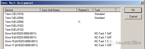
Assuming there are 4 drivers, all connected to a 2MS cycle NC axis. The default synchronization unit setting has two Ethernet frames, with Cycle being 2MS and 10MS. In the 2ms Frame, the LRW instruction (Cmd) has 1 and Len is 56.

Click on Sync UnitAssignment, and the default setting can be seen as:
b. Modify Sync Unit.
Select an AX5203, and directly enter characters in the Sync Unit Name field to specify the synchronization unit name.
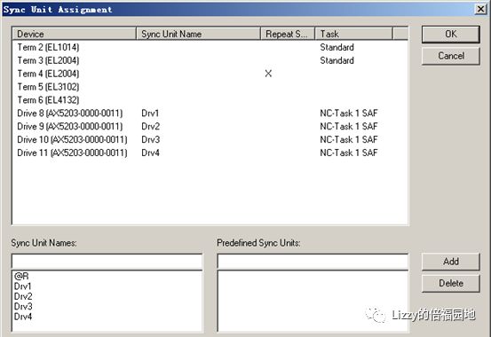
c. Click OK to return to the main interface.
When specifying the 4 drivers as different synchronization units, the Ethernet frames are two, with Cycle being 2MS and 10MS. In the 2ms Frame, the LRW instruction (Cmd) has 4, and Len is 20, 12, 12, 12, with a total length still being 56 bytes.

2.4 Disabling the WcState of servo drives
Customers often report the field NC axis fault 0x4655 (18005), with the prompt message being: Data Invalid Exceed 3 Cycles, which means that data is invalid for three consecutive cycles. Here, the invalid data is due to the Working Counter error of the synchronization unit, indicating that at least one slave in the synchronization unit has not successfully read and written data. If independent synchronization units are assigned, but a certain axis still reports this error, it is usually caused by EtherCAT communication interruptions.
Motion control is highly sensitive to communication, and the default setting for ETHERCAT type NC axes is that once there are 3 NC cycles of invalid data (Data invalid), the NC axis will report an error. If the network quality is poor and there is significant interference on-site, users may want the control system to ignore such occasional communication anomalies, then the variable Clear Link can be set. As shown in the figure:
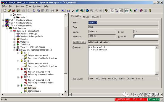
After canceling this link, if the WcState still remains invalid, then the driver or NC axis will report a higher-level fault, such as excessive following error.
3 Checking EtherCAT network grounding
Diagnosing EtherCAT faults is one aspect. Sometimes, some temporary measures can be taken, such as disconnecting the NC axis from the servo drive’s WcState link, but this is just a temporary measure that treats the symptoms rather than the root cause. The fundamental solution is to clarify the source of the problem, including checking grounding, shielding, and other EMC issues.
The first thing to check is: ensure that the EtherCAT network devices share the same ground, as different grounds may cause circulating currents that can lead to data corruption.
4 Setting the driver’s Shift Time
Common errors of servo drives, apart from 0x4655 Invalid Data, include Sync Lost (synchronization loss). This is due to individual cycles of EtherCAT packets failing to arrive within the designated offset time of the synchronization pulse. This error usually occurs on slaves at the end of the network.
To reduce the sensitivity of synchronization signal errors in ETHERCAT communications, the synchronization offset time of the servo drive can be extended. As shown in the figure:
In practical applications, in the vast majority of cases, the default Shfit Time already meets the requirements. Only when the cycle is particularly short (less than 1ms) and the number of nodes is large (greater than 10) is it necessary to manually adjust the Shift Time. When adjusting, it can be incremented by 20% of the master station cycle as a base.
Setting method:
In the slave’s EtherCAT page, click on Advanced Settings, and in the DistributedClock page, set the Sync 1 Shift Time.
5 Hot Connect settings
If using CU2008 or EK1122 to form a star network, you can set Hot Connect Group, so that disconnecting the network cable of any driver will not affect the operation of other drivers.
In a linear topology, if individual sites need to exit and join at any time, such as bridging some sites without affecting the operation of other slaves, the Hot Connect function can also be considered.
For specific implementation methods, see the document:
Http://www.baclizzy.com.cn/20180320EtherCAT hot connection/
EtherCAT network hot connection (HotConnect) settings.pdf
6 EL module layout principles
As a DC reference clock, the EL module should be installed as close to the master station as possible.
EL modules that consume more Ebus current should be installed as dispersed as possible in the IO station to avoid concentrated heat generation.
Typical high-power consumption modules are EL6xxx communication modules, while typical low-power consumption modules are EL1xxx and EL2xxx digital modules.
(To be continued, LizzyChen 2018)
(******************************)

If you like this article, scan the QR code to follow the public account
This public account’s supporting document: ftp://baclizzy.com.cn:21
Support IE access: http://www.baclizzy.com.cn
-Past reviews