Maintain curiosity about technology, broaden the boundaries of knowledge, and enhance the resolution of understanding.
This is not a rigorous academic paper, but rather an explanation of the author’s understanding of EtherCAT distributed clock technology from an industrial application perspective. As an EtherCAT user rather than a developer, many descriptions of this technology may seem superficial. I am willing to be practical, apply what I’ve learned, and use words to reveal errors and receive corrections from professionals. Through writing, I will introduce application experiences and potential analyses, covering a wide range of topics in a shallow manner, believing that all colleagues in industrial control can understand and perform more exciting and in-depth interpretations in their familiar fields.
For more detailed information on the following topics, please read my document sharing links:
http://www.baclizzy.com.cn/20180422 EtherCAT optimization settings
1_EtherCAT Functional Principle_cn
Page3: ESC‘s structure and functional principles
3_EtherCAT Synchronization –cn.pdf
Page6-12: The differences between three synchronization modes
Page27: Accurate calculation of EtherCAT network refresh time
Page61-66: DC Synchronization process
Page71-83: DC synchronization between different networks
Abstract: This article elaborates on the principles of EtherCAT distributed clock technology, introduces the operational modes of distributed clock components, and the hardware products implementing this technology. By linking theory with practice, it discusses the feasibility of achieving sub-microsecond clock synchronization on a general control platform, as well as the broad prospects this technology brings to general manufacturing. This article also lists various industrial site applications, demonstrating how to utilize EtherCAT distributed clock technology to achieve higher levels of automation.
The content is organized as follows:
0. Introduction
1. Principles of EtherCAT Industrial Ethernet
a) Single master station design based on IEEE802.3 standard Ethernet communication
b) Network node addressing and slave station data packet processing mechanisms
c) Calculation of data packet refresh time
d) One network to the end, directly to the IO module
2. EtherCAT Distributed Clock Technology
3. Distributed clock working modes of EtherCAT slaves
Free Run
synchronize with SM event
synchronize with SYNC event
4. Sub-microsecond signal capture and precise control based on DC clock
a) Sub-microsecond signal capture
b) Sub-microsecond precise control
5. Microsecond oversampling technology based on DC clock
a) Subsampling multiples of oversampling technology
b) Applications of oversampling digital modules
c) Applications of microsecond analog oversampling
d) Oversampling power measurement module:
e) Oversampling encoder module
6. EtherCAT cross-network and cross-system DC clock synchronization
DC synchronization between multiple networks of the same controller
DC synchronization between multiple controllers
DC synchronization between different regions and systems
7. Conclusion
(*The main text exceeds 10,000 words, please select interesting sections to read*)
The full PDF is saved at the shared URL:
http://www.baclizzy.com.cn/20180512 EtherCAT Distributed Clock Technology and Industrial Applications
(***********************************)
0 Introduction
When it comes to clock synchronization, people often think of measurement and control fields and communication fields. In these fields, the precision of clock synchronization directly affects system performance indicators and even the entire system’s availability, requiring expensive professional equipment to achieve ns level clock synchronization. With the advancement of technology, the manufacturing field has also generated a demand for clock synchronization. To improve production cycles and product quality, that is, to enhance the speed and precision of individual machines, all action units and sensors must coordinate perfectly. Moreover, multiple controllers on large production lines must exchange data based on the same time reference to coordinate actions accurately. The coordination of individual machines and production lines raises the demand for clock synchronization within control systems and across systems.
However, even in high-end manufacturing, the cost of communication or measurement and control field professional equipment is unaffordable. Since the 21st century, field-level communication technology has matured and become widespread, and high-speed sensors and actuators have been extensively used in commercial applications, but the clock synchronization problem between different devices has not been well solved. The precision of clock synchronization has become a bottleneck limiting further improvements in equipment performance in the general manufacturing field. EtherCAT bus and the distributed clock technology based on EtherCAT break this bottleneck, achieving 0.1µs level synchronization precision at the price level of general control systems, providing technical possibilities for a new level in general manufacturing. This article aims to introduce the principles of EtherCAT distributed clock technology and the performance that can be achieved by devices when used in industrial sites.
1. Principles of EtherCAT Industrial Ethernet
a. Single master station design based on IEEE802.3 standard Ethernet communication
EtherCAT bus is based on 100M Ethernet, using a master-slave design. EtherCAT master station hardware uses standard Ethernet cards, while slaves use dedicated ASIC or FPGA chips to process EtherCAT data packets.
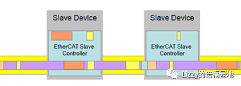
EtherCAT uses standard Ethernet frames ( IEEE802.3 ), but employs a single master station design. In the entire network, only the master station has the authority to decide when to send data packets, while all slaves must wait for the data packets to pass through to extract and insert their own data, as shown in the figure:
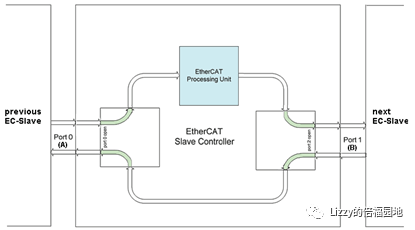
A simple EtherCAT slave chip has only one inlet ( PortA ) and one outlet ( Port B ). As shown in the figure:
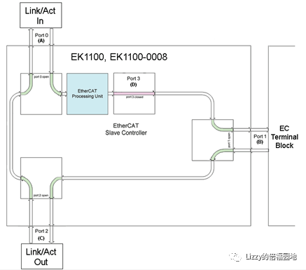
Some EtherCAT slaves have 3 ports: inlet ( Port A ), outlet 1 ( Port B ), outlet 2 ( Port C ). As shown in the figure:
Some EtherCAT slaves have 4 ports: inlet ( Port A ), 3 outlets ( Port B , C , D ). As shown in the figure:
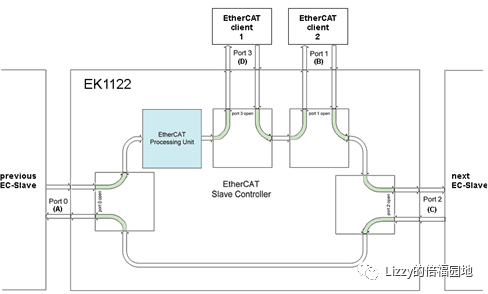
Regardless of how many outlets there are, there is always one inlet, and the direction of the data packet flow is always fixed. Data packets from the master station always flow from Port A , through the EtherCAT Processing Unit to the first outlet, and if available, sequentially to the second, third outlets, and then to the next slave’s inlet Port A . After reaching the last slave, the data packet returns to the master station from the last slave’s outlet back to the inlet Port A of this slave, and then to the last slave’s outlet. Since there is only one master station in an EtherCAT network, and the master station controls all the initiation of data packets, there will be no data packet conflicts in the system. Therefore, as long as the network topology is configured correctly, and the size of each slave’s process data is determined, the size of the entire data packet and its path through the network are also determined, thus the communication time of the entire network is also determined.
b. Network node addressing and slave processing data packet mechanisms
Under normal circumstances, the master station identifies the slaves based on their physical connection order in the network. EtherCAT master station informs each slave of the starting byte and length of its process data in the data packet during the network initialization phase. When the data packet passes through the slave’s interface chip, non-local data is directly allowed to pass through, and from the starting byte of local data, the EtherCAT chip copies the specified number of bytes into its input buffer and inserts the data prepared in its output buffer into the data packet. The entire data packet reaches the last slave and returns to the master station; all slaves extract the output data from the master station, and the master station also receives the input data from all slaves, completing a full refresh process of process data.
Note that the EtherCAT master station can configure the Input and Output data in the data packet to use the same data segment or two separate segments. Beckhoff control software TwinCAT defaults to using the same data segment for the slave’s Input and Output , meaning that when the data packet enters the slave, this data segment contains the Output data sent from the master station, and when it leaves, it contains the Input data sent back to the master station. This setting allows for more efficient communication. If the lengths of the Input and Output data differ, longer byte counts will be reserved in the Frame.
c. Calculation of data packet refresh time
The process data from all slaves in the data packet determines the length of the data packet. An Ethernet data packet has a minimum size of 84 bytes; if less than 84 bytes, it will be padded to 84 bytes. Since there are some common overheads in the EtherCAT Frame, the 84-byte data packet can contain a maximum of 18 bytes of process data. Considering that the data packet must pass through each slave twice to return to the master station, the time taken for the data packet to transmit twice over the network at a fixed baud rate of 100Mbps is the total bus refresh time. Based on this principle, taking a data packet containing 1000 digital signal channels as an example, the calculation process is as follows:
Process data length: 1000/8=125 Byte.
Data packet length: 84-18+125=191Byte=191*8 Bit =1528 Bit
Total bus refresh time: (1528 Bit/100,000,000Bps)*2 =15.28µs *2=30.56µs
Note that typical digital modules are purely output or input modules, not mixed modules, so for 1000 digital signal channels, the Frame will allocate 125 bytes.
Taking a data packet of 100 EtherCAT servo drives as another example, if each servo’s process data includes only a control word ( 2 bytes), a status word ( 2 bytes), a target position ( 4 bytes), and an actual position ( 4 bytes), the calculation process for the total bus refresh time is as follows:
Process data length: 100*(2+4)=600 Byte.
Data packet length: 84-18+600=1266Byte =671*8 Bit =5328 Bit
Total bus refresh time: (5328 Bit/100,000,000Bps) *2=100.656µs
Note that the Frame allocates only 6 bytes for one servo because according to Beckhoff control software TwinCAT default settings, the slave’s Input and Output use the same data segment, meaning that when the data packet enters the servo drive, this data segment contains the control word and target position, while it contains the status word and actual position when it exits.
The two data values 30.56µs and 101.28 µs are derived from the official EtherCAT promotional materials, stating that refreshing 1000 digital signals takes 30µs and refreshing 100 servo axes takes 100µs. In reality, depending on the type of slave, whether it includes a distributed clock, whether clock synchronization is enabled, and the parameters set for clock synchronization, the data packet may also increase by 8-12 bytes to transmit synchronization clock values, and a corresponding Bit mark for each slave, etc., which may add several microseconds to the refresh time, but can be temporarily ignored.
The above calculations only represent the theoretical time required for data packet transmission; in practice, each slave introduces a brief hardware delay when the data packet passes through it. A 100M Category 5 cable interface slave has a delay of about 1µs , while the EBus IO module class slave has a delay of about 0.3µs . In millisecond-level control tasks, if the number of slaves is large, this time can be quite significant, and should be taken into account when calculating refresh cycles.
d. One network to the end, directly to the IO module
An EtherCAT network can connect a maximum of 65535 slaves, far exceeding the maximum number of slaves allowed by previous field buses, which are 32, 64, 127, or 255. According to the previous calculations, the refresh time of EtherCAT is mainly affected by the number of process bytes in slaves, while the impact of the number of nodes is minimal. If we do not consider the hardware delay of data passing through slaves, the bus refresh time is almost the same whether the same process data is distributed over 10 slaves or 100 slaves. The vast majority of control systems will not exceed 1000 IO modules, so EtherCAT allows each IO module to occupy an address, and each IO module is an EtherCAT slave.
If using IO modules with EtherCAT interfaces, backplane communication and communication between the IO stations and the controller use the same protocol, allowing data to flow directly from the controller to the IO module. This is known as “one network to the end.” This is something that other field buses with a maximum of 255 slaves cannot achieve. The implementation of “one network to the end” greatly reduces the transmission links between field signals and controllers, making true high-speed response possible.
2. EtherCAT Distributed Clock Technology
When there are multiple real-time clocks distributed across different hardware in the network, it is called a distributed clock ( Distributed Clocks ). In an EtherCAT network, not only does the master station have a clock, but slaves can also have local clocks. The master station clock usually comes from the CPU clock of the controller, while slaves use the built-in 32 bit or 64 bit distributed clocks in the EtherCAT chip. Usually, the first slave connected to the master station’s distributed clock is regarded as the system master clock (also known as the “reference clock”), which synchronizes the master station and other slaves’ DC clocks.
When the system starts, there is a certain difference between the local clocks of each slave and the reference clock, known as the initial clock offset. During operation, due to reasons such as the crystal oscillators used by each slave, there will be slight differences in their timing cycles, known as clock drift. The delay in data frames propagating between each slave is called transmission delay, which includes delays at the physical and link layers. In the distributed clock processing mechanism, these factors are compensated, ensuring that the compensated DC time of the slaves synchronizes with the time of the EtherCAT master station, thus achieving overall clock synchronization in the system. EtherCAT distributed clock precision is 10ns , and synchronization precision is around 15ns . Considering the hardware actions of slaves, the actual input/output synchronization precision of each DC slave in the network can be controlled within 100ns.
What does it mean to control synchronization precision within 100ns in practical applications?
Taking high-speed CNC laser cutting equipment as an example. Because the power of the laser, the material of the cutting material, and the thickness all affect the cutting effect, the cutting speed must be selected according to different situations. If cutting carbon steel with a 1000W laser cutter, for carbon steel materials under 10mm thickness, when the thickness is less than 2mm , the maximum cutting speed can reach 8 meters per minute; when the thickness is 6mm , the cutting speed is about 1.6 meters per minute, while when the thickness is 10mm , the cutting speed is about 0.6-0.7 meters per minute. The linear speed is related to both the process and the transmission. Taking the higher cutting speed of 8 meters per minute as an example, the position synchronization precision is calculated as follows:
Speed 8000mm/min=133mm/s
=0.133mm/ms=0.133um/µs
Synchronization time precision 100ns=0.1µs
Synchronization position precision 0.133*0.1µs=0.0133 um
A synchronization error of less than 0.02um is almost negligible compared to position errors caused by mechanical transmission, which is sufficient to meet the requirements for high-speed and high-precision processing.
3. Distributed clock working modes of EtherCAT slaves
EtherCAT slave chips periodically execute calculation and data copying tasks in sequence, with working cycles ranging from several microseconds to several milliseconds. Through the parameters of the distributed clock, it is possible to accurately set the refresh output and input reading times for each EtherCAT slave, ensuring that the input signal values received by the master station from different slaves are obtained simultaneously, and that the output signals sent to different slaves from the master station can also trigger the connected output circuits at the same time.
EtherCAT slaves with distributed clocks can set their working modes:
Free Run, the EtherCAT slave does not synchronize with the EtherCAT master station. Each slave triggers input or output independently, unrelated to the reference clock.
synchronize with SM event, the EtherCAT slave triggers the action to read input or refresh output when it detects that a data frame has passed. If the data frame contains Output data from this station, it triggers the SM2 event; if the data frame contains only Input data, it triggers the SM3 event.
synchronize with SYNC event, the EtherCAT slave determines the time to read input or refresh output based on the local DC clock’s synchronization pulse SYNC0 or SYNC1 .
The parameters of the EtherCAT slaves are stored in E2PROM , while externally accessible parameters are encapsulated in the form of CanOpen object words. By combining parameters 0x1C32 and 0x1C33, it is possible to determine the working mode of the distributed clock.
Below are detailed introductions to various working modes:
a. Free Run mode: The LocalTimer Event of the slave determines the start time of various tasks. Once the event is triggered, it immediately outputs, obtaining input a short time before the Min Cycle Time.
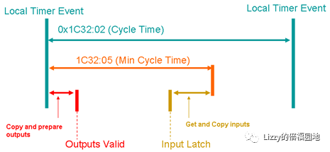
The interval of the Local Timer Event is consistent with the task cycle preset by the controller, but its triggering time is independent of the master station, so the reading time of input signals and the triggering time of output circuits cannot be determined.
b. Synchronous with SM eventmode (without Shift parameter)
The SM2/3 event triggered by the passage of the message determines the start time of various tasks; once the event is triggered, it immediately outputs, obtaining input a short time before the Min Cycle Time.
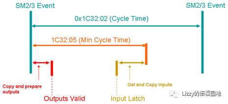
The interval of the SM2/3 event is consistent with the task cycle preset by the controller, but its triggering time depends on when the data packet from the master station arrives at this slave. Using this method allows the output signal to trigger the output circuit as quickly as possible, resulting in slaves closer to the master station completing the output status refresh earlier.
c. Synchronous with SM eventmode (with Shift parameter)
The SM2/3 event triggered by the passage of the message determines the start time of various tasks; it immediately outputs, but after a delay of Shift Time to obtain input.
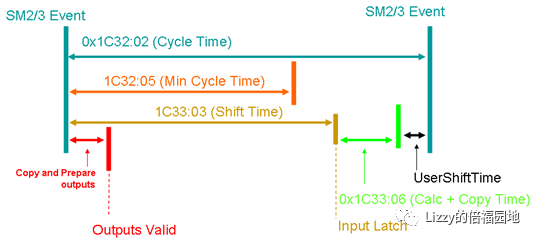
Compared to the Synchronous with SM event mode without the Shift parameter, the difference lies in that the input signal reading time can be set as a delay from the SM event, but it must exceed the minimum cycle time required by the hardware. Since the timing of when the data packet is sent by the master station and when it arrives at this slave can fluctuate, there is also no synchronization among slaves using this method.
d. Synchronous with SYNC eventmode (without Shift parameter)
The Sync0 event triggered by the slave’s DC clock determines the start time of various tasks; it immediately outputs after the Sync0 event is triggered and obtains input a short time before the Min Cycle Time. This is independent of when the Frame passes through the slave.
Due to the clock synchronization mechanism of EtherCAT, all slaves’ DC clocks’ Sync0 signals are triggered simultaneously, and the difference between any two slaves’ DC clock Sync0 signals does not exceed 100ns. Therefore, in this mode, the difference in refresh times of the output circuits of any two DC slaves depends on their respective 1C32:06 (Calc+Copy Time) and 1C32:09 (Hardware Delay Time). If the hardware is of the same model, these times are almost identical; if they are of different models, there will be differences. Similarly, the time for obtaining input signals will be the same for hardware of the same model, otherwise different.
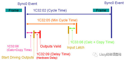
e. Synchronous with SYNC eventmode (with Shift parameter)
The Sync0 event triggered by the slave’s clock determines the start time of various tasks; after the Sync0 event, calculations and memory copying occur immediately, but the hardware is not driven until after a delay. The delay time is the output Shift Time (0x1C32:03) minus the time required for hardware state switching. For input signals, this is after the Sync0 event with a delay of Shift Time (0x1C33:03) minus the time required for hardware state acquisition, triggering the state acquisition ( Start Latch ) action. As shown in the figure:
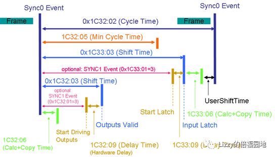
Compared to the Synchronous with SYNC event mode without the Shift parameter, this method can compensate for the differences in 1C32:06 (Calc+Copy Time) and 1C32:09 (Hardware Delay Time) due to different hardware models by adjusting the Shift Time to ensure that the final output circuit refresh times of the target DC slaves are strictly consistent. Of course, the set 1C32:03 (Shift Time) must be greater than the sum of the time required by the hardware for 1C32:06 (Calc+Copy Time) and 1C32:09 (Hardware Delay Time). Similarly, the set input delay time must also consider the time required for hardware input conversion.
Some EtherCAT slaves come with two distributed clocks, which can trigger two events: Sync0 and Sync1. Sync1 remains synchronized with other DC slaves, while Sync0 is used to drive hardware outputs. Sync0 will trigger after a delay of Output Shift Time (0x1C32:03) – Hardware Delay time. For example, in Beckhoff’s output module EL2252, when 0x1C32:01=3, the data packet sent by the master station should include the specific time for triggering hardware refresh, and each communication cycle, the slave extracts this time from the received data packet and calculates to obtain the accurate value of Output Shift Time (0x1C32:03), thus controlling the switching time of the output signal state within 0.1µs.
f. Synchronous with SYNC eventmode (with Shift parameter and sub-clock function)
Some EtherCAT slaves come with two distributed clocks, which can trigger two events Sync0 and Sync1. By setting the subdivision multiple n, the period of Sync0 is averaged out to n equal parts of the period of Sync1. The clock of Sync0 is called a sub-clock, and within one period of Sync1, it triggers output and input actions n times.
Each action follows the same principles as the Synchronous with SYNC event mode (with Shift parameter).
As shown in the figure:
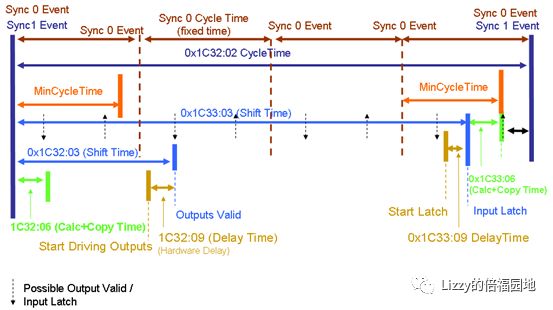
Through the overlapping effects of the two clocks, n samples or outputs can be completed within one Sync1 period. The period of Sync1 is equal to the control period, which is limited by the computational performance of the master CPU and the minimum task cycle of the control software, while the period of Sync0 that triggers hardware actions is limited by the hardware circuit conversion time and the operation and copying time of the slave chip. Therefore, in Beckhoff’s EtherCAT slave products, the period of Sync1 can only reach 50µs at the minimum, while the period of Sync0 can be as low as 1µs (for digital modules) or 10µs (for analog modules).
4. Sub-microsecond signal capture and precise control based on DC clock
a) Sub-microsecond signal capture
Signal capture, also known as signal latching, is typically available on encoder interface modules or servo drives, which have latching input points that immediately latch the current count value of the encoder on the rising or falling edge of the input signal, and then transmit the latched value to the master station via the bus after the next communication cycle, such as several ms later. This method has the advantage of precise capture, but the disadvantage is that the latched signal must connect to the module where the signal to be latched is located.
Based on EtherCAT distributed clock technology, Beckhoff provides a digital input module with functions EL1252 . It sends not only the current status of the channel to the master station but also the rising and falling edge trigger times of the channel, referred to as TimeStamp. Since all DC clocks in the system remain synchronized, the master station can utilize this ns level to trace back to the process variable values of other DC slaves at that time, such as counts, pressure, position, etc., effectively achieving signal capture indirectly.
The advantage of using the EtherCAT module EL1252 for signal capture is that it does not depend on the device being captured; the capture signal connects to the IO module instead of the device being captured, and a single capture signal can simultaneously capture process variable values from multiple devices. Moreover, the capture precision is comparable to hardware capture. The capture precision is unaffected by the controller cycle; even with an economical CPU, such as a control cycle of 10ms or even longer, sub-microsecond level signal capture can still be achieved.
In the industrial manufacturing field, the most typical application of sub-microsecond signal capture based on EtherCAT distributed clock technology is the software probe function, used to replace traditional hardware probe functions, such as color mark capture on packaging printing equipment. The color mark sensor signal can be connected to the DI module, as shown in the figure:
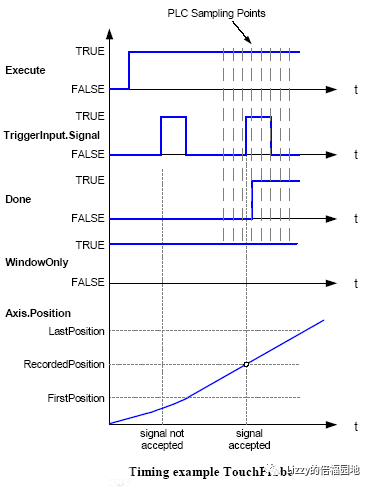
In the image above, the effective rising edge of the sensor signal occurs between the two sampling points of the controller, and the program can accurately calculate the corresponding Axis.Position value at that moment based on the rising edge signal returned by the module.
In addition, Beckhoff’s newly launched module EL1259 also supports recording up to 10 rising edges within one control cycle, a function that can be used to count pulse numbers and calculate pulse frequencies, etc.
b) Sub-microsecond precise control
Corresponding to sub-microsecond signal capture is sub-microsecond precise control.
Traditional control refreshes the hardware output state once each control cycle. The usual working sequence is “read – compute – output.” For the same hardware system, the reading and output times do not fluctuate significantly, but the computation time of each control cycle can vary due to different input conditions. Therefore, the actual response time of the hardware output will fluctuate within one control cycle. To precisely control the action of a hardware device, the common approach is to use output points built into the computation chip directly. For example, the output points that come with the counter module, which are set directly when the count is full, without passing through the controller. Another example is the zeroing of the servo drive’s position signal once the signal is captured.
This implementation method requires not only that the output points must use the module’s output pins directly, but also that algorithms must be implemented within the module. This means that users can only use the output and input signals pre-designed within the module. For example, servo drives typically reserve origin, positive limit, negative limit, and position latching signals, where the origin and position latching signals have ns level responses, while outputs usually relate to alarms and readiness, but are not position-related.
Beckhoff provides a digital output module with timestamps EL2252. The master station can set the precise time StartTime for switching the output channel state and the target state to be switched. Since all DC clocks in the system remain synchronized, the master station only needs to precisely control this ns level time StartTime, to switch the output channel when the sampling signal of a certain DC slave just reaches the target value.
Sub-microsecond precise control is most typically applied to digital outputs related to high-speed motion, including:
Cam output: that is CamSwitch, which can precisely control a digital output channel to open and close within the specified position interval of a high-speed moving axis. For example, using this signal to control the camera shutter to open is called “flying shot”(Flying Shot).
Flying cutting: CNC laser cutting equipment aims to improve processing efficiency by not cutting a closed curve at once, but rather cutting multiple line segments in succession to form a preset shape. For instance, processing 10 parallel square holes, each with a side length of 10mm and a spacing of 15mm. Typically, the laser head moves in a straight line relative to the workpiece at a constant speed, turning on and off the light sequentially for 10 times, thus processing 10 line segments. In CNC laser cutting equipment, using high-speed output modules to control the switching of the laser head is referred to as flying cutting.
Using the output module EL2252 with DC clock to achieve precise output, the control precision reaches 100ns , but there are no requirements for the control cycle; even with an economical CPU, such as a control cycle of 10ms or even longer, a control precision of 100ns level can still be achieved.
5. Microsecond oversampling technology based on DC clock
EtherCAT chips with oversampling functions have two DC clocks, one generating synchronization pulses with the same frequency as the master station’s task cycle, while the other serves as a sub-clock to produce sub-pulses n times the frequency of the synchronization pulses. The time to trigger input acquisition or refresh output based on the sub-pulses results in an actual sampling period that is n times shorter than the control period. As shown in the figure:
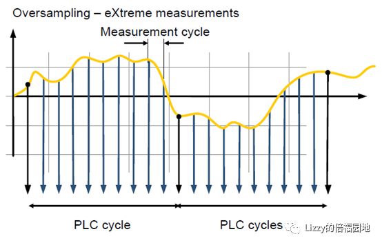
The above figure illustrates one analog signal being sampled 10 times within one PLC cycle, resulting in an actual sampling period ( Measurement Cycle ) that is one-tenth of the control period ( PLC cycle ).
In oversampling technology, the maximum subdivision factor for the Sync0 sub-pulse is limited by the action frequency of the hardware circuit. The subdivision factor is also limited by the minimum cycle of the module’s circuit conversion: the minimum cycle for oversampling digital modules is 1µs , for oversampling analog and encoder modules is 10µs , and for oversampling power monitoring modules is 100µs. Since controller cycles are typically measured in milliseconds, even for real-time cores controlled by PCs, the minimum control cycle can only reach 50µs , requiring a high-performance CPU. Using Oversampling technology allows for µs level input and output cycles without requiring a high-performance controller.
Below are several hardware and applications based on oversampling technology:
a) Oversampling digital module applications
Based on EtherCAT distributed clock technology, Beckhoff provides digital modules with oversampling functions, including input module EL1262 and output module EL2262, which can achieve a sampling frequency of 1MHz when the controller cycle is 1ms. These modules can perform similar tasks, such as probe input, cam output, flying shot, flying cutting, etc. The advantage is that multiple changes can occur within one controller cycle, while the disadvantage is that the theoretical time precision is not as good as that of the module. However, considering overall system errors, there is almost no difference in practical applications between 1µs and 100ns time precision.
Additionally, the oversampling digital module can also count the number of pulses over a specified time period and calculate pulse frequencies, such as measuring the speed of wind turbine blades in the wind power industry, or processing pulse flow meter signals in beverage packaging systems.
b) Microsecond analog oversampling applications
Based on EtherCAT distributed clock technology, Beckhoff provides analog modules with oversampling functions, including standard current/voltage signal input/output modules. When the controller cycle is 1ms , a sampling or output frequency of 100kHz can be achieved. This frequency level can be used not only in advanced manufacturing fields of factory automation but also in low-end measurement and control fields. For example, a simple electronic oscilloscope: each control cycle can have 100 values entering the controller, and by writing controller code to process this data, historical extreme values can be obtained, curve records stored, and playback achieved. Algorithms can also be written for state analysis, such as collecting vibration data from critical bearings for preventive maintenance.
Moreover, the module can trace back to the instantaneous values of analog signal devices with DC clocks, and the denser the sampled points being traced, the more accurate the traced values. Therefore, combined with oversampling technology, more precise tracing of important analog signal values, such as instantaneous pressure, instantaneous acceleration, and instantaneous torque, can be achieved. Combined with EtherCAT drives or encoder modules with distributed clocks, it can also reproduce the “analog – position” curves in the controller, such as pressure-position curves in injection molding machines, die-casting machines, and ceramic pressing machines; torque-position curves in tightening machines.
Oversampling output modules can also be used as signal generators, capable of generating waveforms below 50kHz, including regular curves such as square waves or sine waves, with adjustable amplitude, frequency, phase, and offset. It can also combine recorded events for playback, outputting irregular waveforms to simulate field conditions, reproduce problems, and analyze fault causes.
c) Oversampling power measurement modules:
The oversampling power module is another application based on EtherCAT distributed clock technology from Beckhoff. Traditional power measurement modules are used to replace power meters by directly measuring three-phase voltage and current, calculating power, frequency, energy consumption, and other electrical quantities. If we do not consider differences in transmitter links, we can understand the three-phase voltage and current input channels of the oversampling power module as 6 oversampling analog signal channels. Relying on EtherCAT ‘s high-speed transmission and the dual DC clock’s oversampling technology, the power measurement module separates the functions of traditional power measurement instruments: the collection of raw voltage and current signals is placed on the IO module, while the functions of calculating power factor, power, energy consumption, and harmonic analysis are placed on the controller. The benefit of this approach is to fully leverage the computational power of the controller, allowing the PC to undertake more computational tasks, thus saving costs on the IO part. On the other hand, PC computation also increases the transparency of power analysis, opening up the black box of power measurement. Electrical engineers can explore lower-level data and conduct more secondary analyses.
d) Oversampling encoder modules
The oversampling encoder module EL5101-0011 is another application based on EtherCAT dual DC clocks, with a maximum subdivision factor of 100. When the encoder is used as a position feedback device for motion control, sampling the position once per control cycle is sufficient. But under what circumstances is it necessary to sample 100 position data points per cycle? Taking the “position – pressure” curve in die-casting or injection molding machines as an example, since the position-pressure curve strictly affects the forming quality of the press, and the pressure increase process is extremely short, often just a few tens of milliseconds. To obtain enough sampling points, if using a regular encoder module, the control cycle must be set very short. However, using the oversampling encoder module, it can achieve a sampling frequency of 100kHZ at a control task cycle of 1ms, yielding more realistic and detailed results. This can optimize control strategies and enhance equipment performance.
6. EtherCAT cross-network and cross-system DC clock synchronization
Cross-network clock synchronization refers to having more than 1 EtherCAT networks on a control system, where the DC clocks of these networks need to be synchronized. For example, two Ethernet cards on one controller leading to two EtherCAT networks, or a gigabit card expanding up to 8 EtherCAT networks through a network multiplier CU2508. This synchronization does not require additional hardware; it can be achieved through corresponding parameter settings in the master station software.
Cross-system clock synchronization refers to projects with multiple control systems that can be interconnected within 100 meters of cable, and each supporting EtherCAT master stations, in which case a bridge module EL6695 can be used to synchronize the clocks of each controller. If not all control systems are EtherCAT master stations, or if these control systems are too far apart to connect via cable, an external clock module EL6688 needs to be added. When all control systems’ clocks synchronize with external clock signals from the Internet, they will naturally synchronize with each other. Both synchronization methods have a precision of less than 1µs.
A typical application of cross-system clock synchronization is in power systems. For wind power generation, if all controllers within a wind farm are EtherCAT controllers, they require clock synchronization, achieved using the EtherCAT bridge module. If clock synchronization is needed between different control systems in the power grid, or between control systems in different regions, then external clock modules EL6688 are added to the EtherCAT controllers, and similar external clock hardware devices are added to other systems.
7. Conclusion
Based on EtherCAT distributed clock technology, traditional control technology bottlenecks have been broken through, allowing general PC control platforms combined with DC clock-enabled IO modules to achieve the sampling and control precision of specialized equipment. This lowers the threshold for advanced manufacturing in the factory automation field, making high-speed, high-precision equipment increasingly popular and potentially elevating the average industry level to a new height. On the other hand, for users proficient in algorithms and analysis, there is no need to invest in expensive specialized equipment; using general products can achieve microsecond-level precision, validating and optimizing their research results. Therefore, in industries where software algorithms and analysis are core technologies, such as measurement and control, vision, and robotics, EtherCAT distributed clock technology is increasingly becoming a foundational technology for their hardware platforms.
(******************************)

If you like this article, scan the QR code to follow the public account
Supporting documentation for this public account: ftp://baclizzy.com.cn:21
IE access supported: http://www.baclizzy.com.cn
-Previous reviews