Follow our public account, click the top right corner of the homepage “ ··· ”, set a star mark, and get real-time updates on the latest news in intelligent automotive electronics and software.
1. Introduction to LIN
1.1 What is LIN?
LIN (Local Interconnect Network) bus is a low-cost serial communication protocol defined for automotive distributed systems.
Compared to the CAN bus, the LIN bus protocol is relatively simple, and the requirements for microcontrollers are not high; a basic serial port can achieve it, thus keeping costs low.
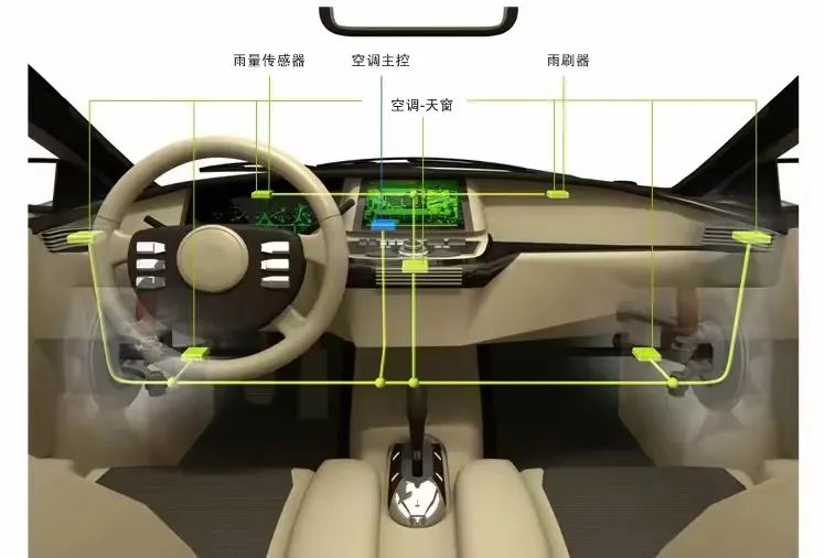
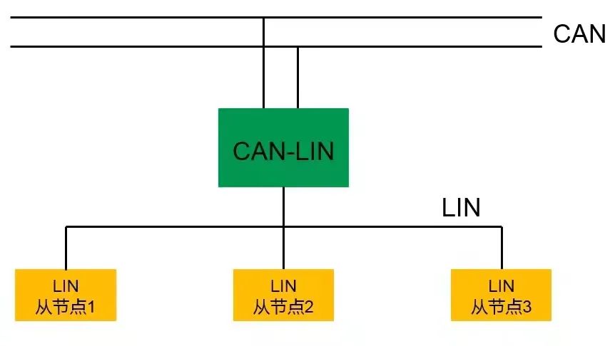
As an auxiliary bus to the CAN bus, the LIN bus complements existing bus technologies and is widely used in body control areas such as doors, windows, lights, and central locking.
1.2 Features of LIN Bus
Single master/multiple slave mode does not require an arbitration mechanism.
Low cost, based on UART serial communication, all controllers have the necessary hardware for LIN.
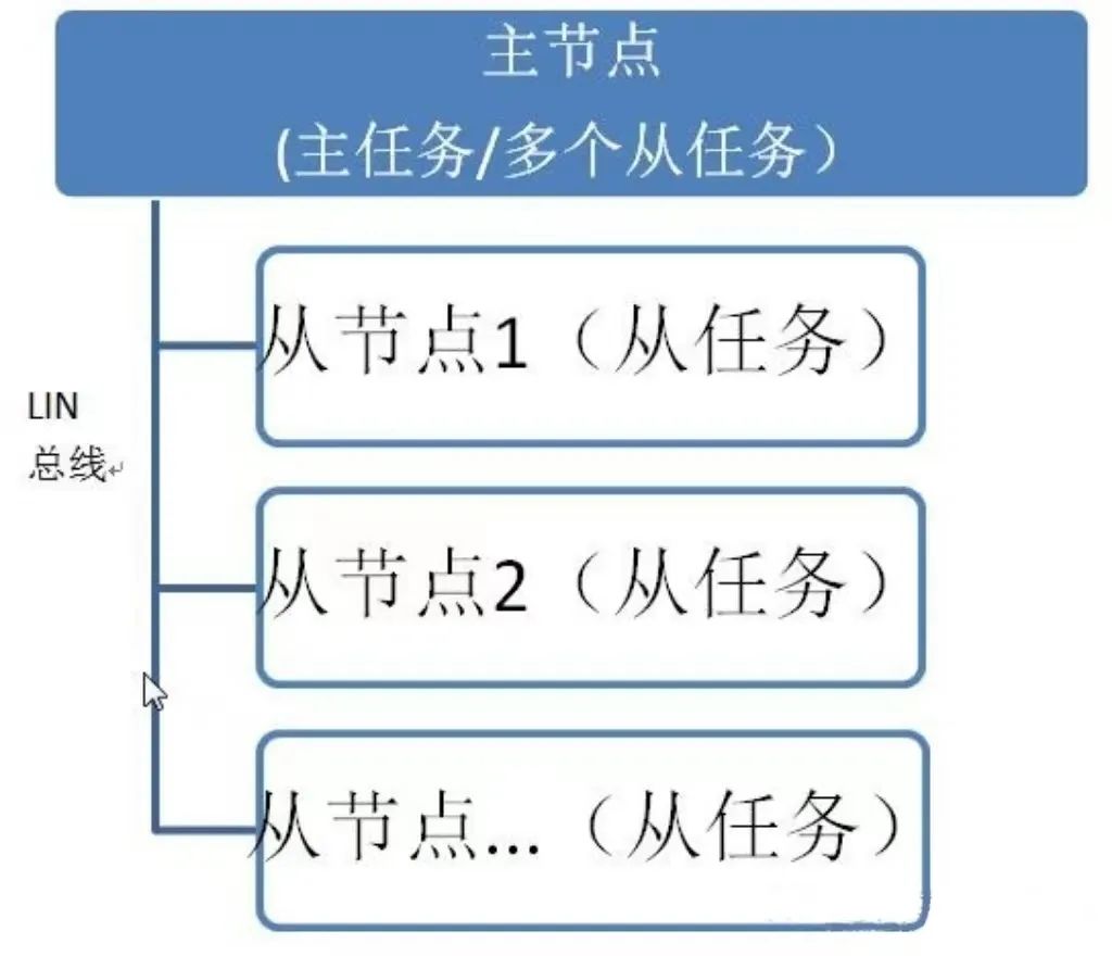
One master node corresponds to multiple slave nodes.
Single signal line transmission, while ensuring the delay time of signal transmission.
LIN has predictable electromagnetic compatibility performance; to limit EMC strength, the LIN protocol specifies a maximum transmission rate of 20kbps.
LIN bus provides configuration, processing, identification, and diagnostic functions for signals.
Supports transport layer and diagnostic functions.
LIN bus has its “local” characteristics, generally not existing independently in vehicles, and usually connected to the upper-level CAN network, forming a CAN-LIN gateway node. Typically, automotive electronics manufacturers will specify the controller belonging to this “gateway node”.
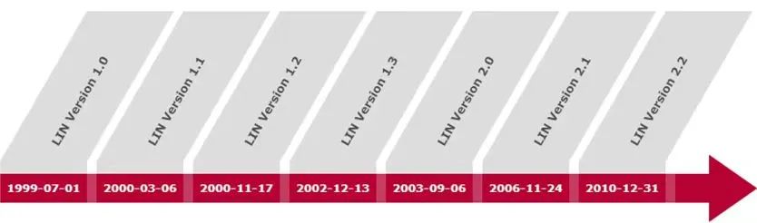
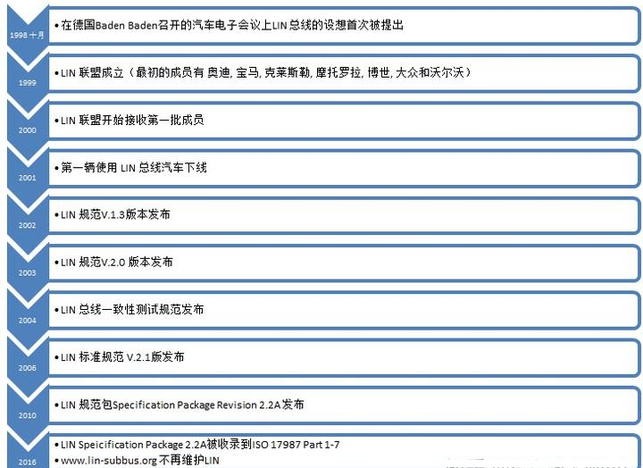
1.3 History of LIN Bus
1.4 Tasks of LIN Bus
1. Schedule the transmission order of frames on the bus.
2. Monitor data and handle errors.
3. Serve as a standard clock reference.
4. Receive wake-up commands sent from slave nodes.
5. Slave tasks cannot directly send data to the bus; they must receive the frame header sent by the master node and determine based on the information contained in the frame header.
2. Basic Concepts of LIN Bus
2.1 Structure of LIN Message Frame
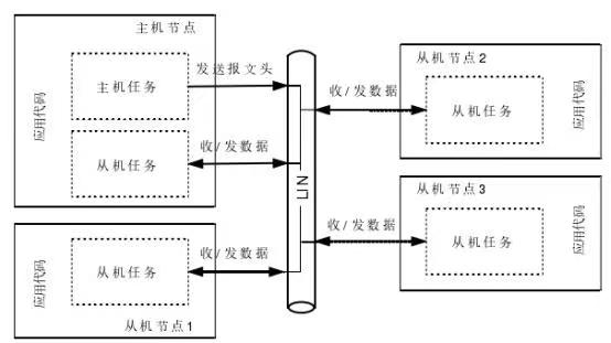
(1) Master Node and Slave Nodes
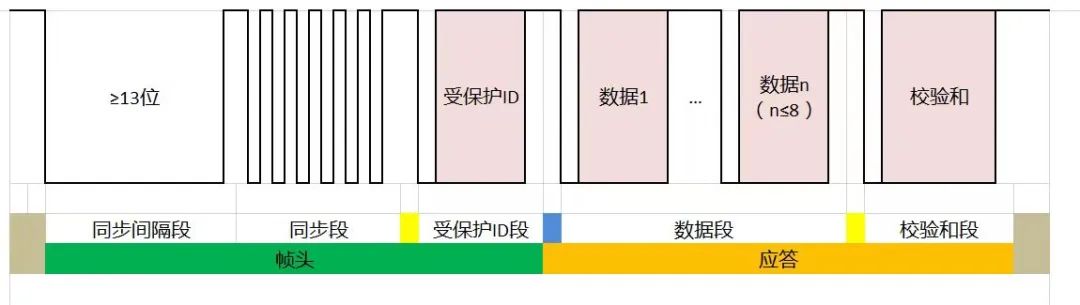
LIN message frame consists of a frame header and a response.
During transmission, the master node is responsible for sending the frame header; the slave node is responsible for receiving the frame header and then deciding whether to send a response, receive a response, or not reply. Slave nodes cannot actively send data.
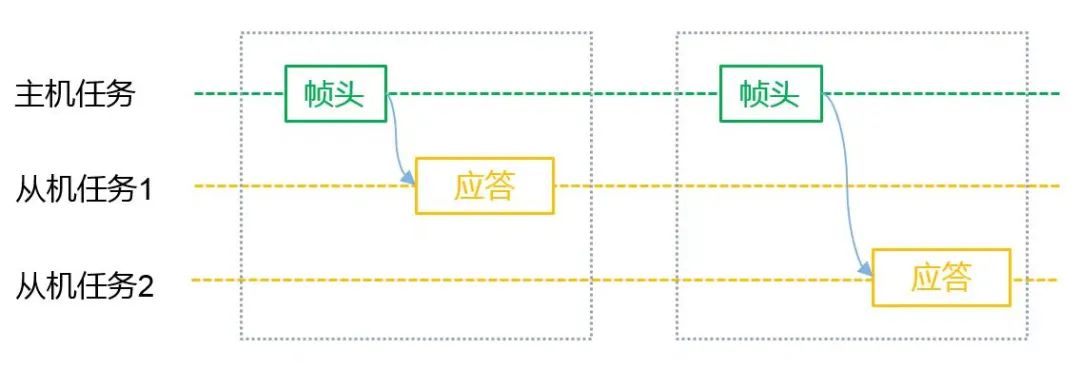
The master node sends the data frame header, and the slave node identifies it based on the frame header and sends the corresponding data to the LIN bus. There will only be one master node on the LIN bus, but there will be multiple slave nodes. The master node has a main task—responsible for scheduling LIN bus messages and a secondary task—responsible for sending data.
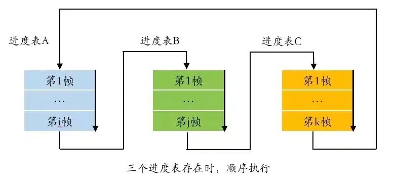
The frame scheduling table (or schedule table) specifies the transmission order and timing of frames on the bus, determining the interval time and order for each message. Therefore, LIN bus communication is predictable. The scheduling table is located in the master node, which decides the timing intervals for sending each message based on the scheduling table. There can be multiple scheduling tables; generally, when a certain scheduling table is executed, it starts from the entry point of that scheduling table and executes until the last frame of the scheduling table. If no new scheduling table starts, it returns to the first frame of the current scheduling table to execute; it may also be interrupted during execution and jump to another scheduling table before returning, such as an event-triggered frame being a typical example.
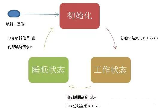
In the LIN bus, slave nodes have three states: initialization state, sleep state, and working state.
① Initialization state: A transitional state after powering on, resetting, and waking from sleep. In the initialization state, the slave node performs necessary initialization in preparation for LIN communication. In the initialization state, the slave node cannot send or receive LIN communication messages.
② Working state: The state of normal operation. In this state, the slave node can normally send and receive LIN communication messages.
③ Sleep state: Stops the normal operation of the LIN transceiver but can accept wake-up signals from the master node and can actively send wake-up signals to the LIN bus (internal wake-up).
The sleep command reuses the diagnostic frame 0x3C, with the first byte as 0 and the remaining 7 bytes as 0xFF.
(3) Frame Header Structure includes sync interval field, sync field, PID field (Protected ID) field, and the response part includes data field and checksum field.
Where “0” is dominant level, and “1” is recessive level, the dominance and recessiveness are the same as in CAN bus. The bus operates on a “wired-AND”: when at least one node on the bus sends a dominant level, the bus presents a dominant level; when all nodes send recessive levels or do not send information, the bus presents a recessive level, meaning that the dominant level takes precedence.
① Sync interval segment (interval field)
All gaps in the frame are recessive level “1”, and the bus remains in a recessive level “1” state when idle, and no other fields in the frame will emit a dominant level greater than 9 bits. Therefore, the sync interval field consists of at least 13 bits (usually 13 or 14 bits) of dominant level. Thus, we can conclude that the sync interval field can indicate the start of a frame. Additionally, the interval of the sync interval field must be at least 1 bit recessive level.
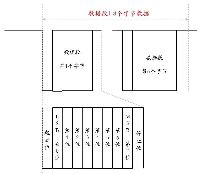
Before introducing the sync segment, let’s first introduce the concept of byte field, which includes 1 start bit (dominant) + 8 data bits + 1 stop bit (recessive), which can be summarized as “dominant starts, recessive stops”, a standard UART data transmission format.In a LIN frame, all segments after the sync interval segment are transmitted in byte field format.In the LIN frame, data transmission sends LSB (Least Significant Bit) first, followed by MSB (Most Significant Bit).LIN bus uses the falling edge as a judgment mark and synchronizes using byte 0x55 (01010101b). Slave nodes can use low-precision clocks such as on-chip oscillators; if there is a deviation, it can be adjusted through the sync field.
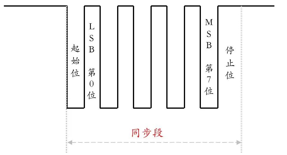
The slave node can use a low-precision clock instead of a high-precision clock, and any deviation caused by this needs to be adjusted through the sync segment. The result of the adjustment is to align the baud rate of the slave node data with that of the master node. The reference clock for synchronization is the clock of the master node. The slave node adjusts its baud rate based on the master node’s baud rate calculated from the received sync segment.
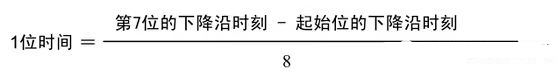
By calculation, we can determine the actual time taken by the master node to transmit 1 bit, which is the bit rate. Calculation formula:
Protected ID, where the first 6 bits are the frame ID, along with two parity bits is called Protected ID.
Frame ID has a value range of 0x00~0x3F, a total of 64, and the frame ID identifies the category of the frame. The slave task will respond based on the frame header ID (receive/send/ignore response), where P0 and P1 checks are as follows:
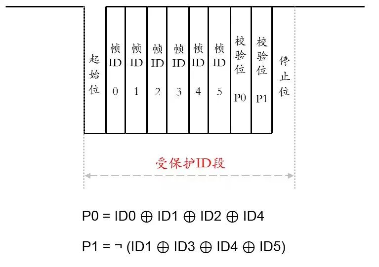
“⊕” represents “XOR” operation, and “¬” represents “NOT” operation. From the formula, it can be seen that PID will not appear as all 0 or all 1, therefore, if the slave node receives “0xFF” or “0x00”, it can be judged as a transmission error.
The range of ID0~ID5 is also specified:
0-59 (0×3B) → general data frame ID range
60 (0×3C); 61 (0×3D) → used for diagnostic commands
60 (0×3E); 64 (0×3F) → reserved
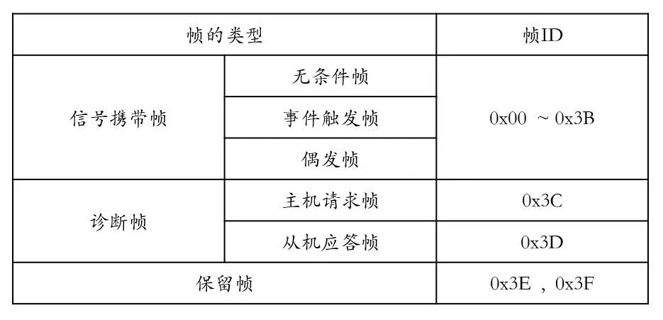
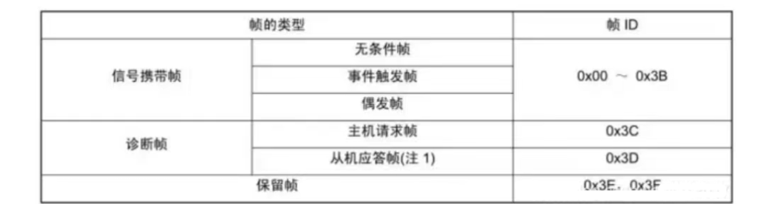
Based on different frame IDs, the LIN bus divides messages into signal-carrying frames, diagnostic frames, and reserved frames.
The slave response frame is a complete frame, which is different from the “response” in the frame structure.
④ Data Field
The data field is the actual data to be transmitted in the LIN data frame. The data field contains 1-8 bytes, with the data transmission order: low byte first, low bit first; if the data length exceeds 1 byte, small-endian mode (low bit sent first) is used.
The data field can be divided into two types, signals and diagnostic messages. Signals are transmitted by signal-carrying frames, and diagnostic messages are transmitted by diagnostic frames. LIN2.x specifies the transmittable LIN byte count as 2, 4, 8, not any number within 1-8. Generally, a uniform byte count is selected for vehicles, with the most common being 8 bytes per frame.
Unlike the CAN bus, the LIN protocol does not specify information about data length; data content and length are predetermined based on frame ID. Data on the bus is broadcast, and any node can receive it, but it is not useful for every node. The specific publication and listening are determined by the configuration of the application layer.
In general, during the response of a frame, there is only one publishing node on the bus; otherwise, an error will occur. Event-triggered frames are an exception, as they may have 0, 1, or multiple publishing nodes.
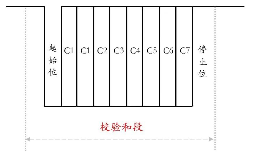
The checksum field is used to verify the content of frame transmission to enhance data reliability.
Verification can be standard checksum (checks only the data field, not the identifier field) or enhanced checksum (checks both the data field and the identifier field).

The choice between standard and enhanced is managed by the master node, and publishing and listening nodes determine which checksum to use based on frame ID.
2.2 Types of LIN Frames
According to the LIN2.1 specification, there are the following types of LIN frames:
Unconditional frames, event-triggered frames, sporadic frames, diagnostic frames, reserved frames
Different frame ID ranges for different frames:
(1) Unconditional Frame (0-0×3B)
The unconditional frame is one with a single publishing node, and regardless of whether the signal changes, the frame header will be unconditionally responded to.
The unconditional frame is transmitted in the fixed frame time slot assigned to it by the master task. Once a frame header is sent on the bus, a slave task must respond (i.e., unconditionally send a response).
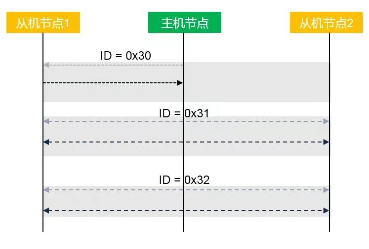
① Frame ID = 0x30, the publishing node in the response part is slave node 1, and the listening node is the master node. A typical application is when slave node 1 reports its signal status to the master node.
② Frame ID = 0x31, the publishing node in the response part is the master node, and the listening nodes are slave nodes 1 and 2. A typical application is when the master node publishes information to slave nodes.
③ Frame ID = 0x32, the publishing node in the response part is slave node 2, and the listening node is slave node 1. A typical application is communication between slave nodes.
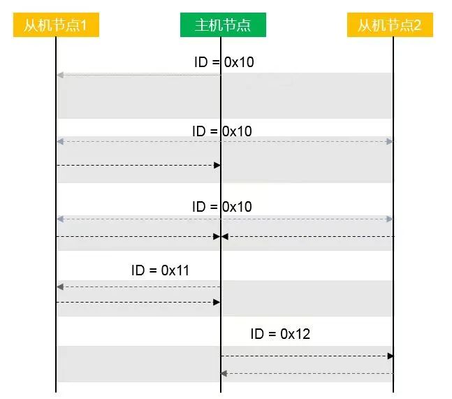
(2) Event-Triggered Frame (0-0×3B)
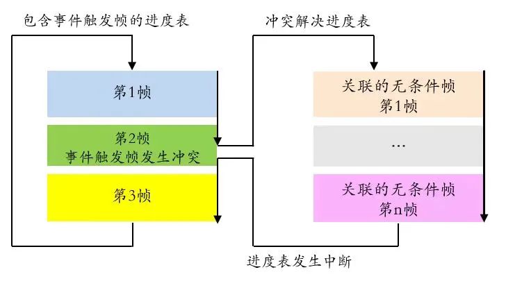
The event-triggered frame must have a unique ID that can be associated with multiple unconditional frames. In the time slot of the event-triggered frame, the frame header is sent only when the associated unconditional frame has updated signals. If there is no frame response, the frame header is ignored. Frame responses can be sent by multiple nodes, and in case of conflict, it switches to the “conflict resolution scheduling table,” and then switches back to the original scheduling table.
The event-triggered frame is used by the master node to query whether the signals of each slave node have changed within a frame gap. When there are multiple publishing nodes, conflicts are resolved through the conflict resolution scheduling table.
When the frequency of signal changes in the slave nodes is low, querying the information of each node repeatedly by the master task will occupy a certain bandwidth. To reduce bandwidth usage, the concept of event-triggered frames is introduced.
The main principle is: When the state of the slave node information has not changed, the slave node does not need to respond to the frame header sent by the master; when multiple nodes have changed their information simultaneously, responding to the event-triggered frame header will cause a bus conflict. When the master node detects a conflict, it will query the conflict resolution schedule to sequentially send unconditional frames (only one node can respond to an unconditional frame) to determine the state of the slave nodes’ information.
Multiple unconditional frames associated with the event-triggered frame must meet the following conditions: the number of data bytes contained in the data field is the same length, and the first byte of the data field must be the protected ID of that unconditional frame. This way, it can be known which associated unconditional frame the response is sent from, and different slave nodes cannot be in the same scheduling table as the event-triggered frame.
(3) Sporadic Frame (0-0×3B)
The sporadic frame indicates a group of ordinary frames that share a time slot and are sent only when needed.The sporadic frame is a frame that the master node initiates to send to the bus when its own signal changes within the same frame time slot.
When multiple associated response signals change, arbitration is done based on predefined priorities. Similar to the event-triggered frame, sporadic frames also define a set of unconditional frames. It is stipulated that sporadic frames can only be published by the master node.
There are three possible situations for sporadic frame transmission:
1) When the associated unconditional frame does not have signal changes, the master does not need to send the frame header.
2) When one associated unconditional frame signal changes, that frame is sent.
3) When multiple unconditional frames change signals, they are sent in order based on the predefined priority.

(4) Diagnostic Frame
The diagnostic frame includes the master request frame and the slave response frame, mainly used for configuration, identification, and diagnostics. The master request frame ID = 0x3c, sent by the master node as the frame header and frame response; the slave response frame ID = 0x3d, sent by the master node as the frame header and the slave node as the frame response. The data segment is set to 8 bytes, using standard checksum.
(5) Reserved Frame
The reserved frame IDs are 0x3E and 0x3F, reserved for future expansion needs.
Source: Automotive Maintenance and Repair, Xue Er Wei Technology
Follow our public account, click the top right corner of the homepage “ ··· ”, set a star mark, and get real-time updates on the latest news in intelligent automotive electronics and software.