
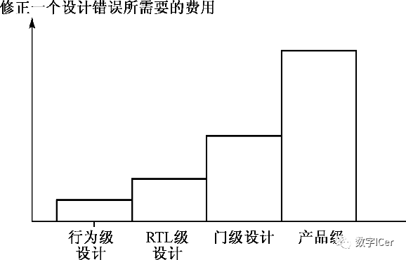
As the design progresses and approaches the final product, the cost of correcting a design flaw becomes increasingly high.
1. Overview of Functional Verification
1. Overview of Functional Verification
In the field of IC design and manufacturing, the terms verification and testing refer to two different processes.
Verification
-
Confirming the correctness of the design during the design process -
Conducted through methods such as software simulation, hardware emulation, and formal verification -
Must be performed before tape-out.
Testing
-
Detecting defects that may have occurred during manufacturing or packaging. -
Carried out using testing equipment.
Functional Verification
Functional verification generally refers to the process where designers compare the completed circuit with the functionality specified in the design documents to ensure the correctness of the logical design.
Typically does not include performance testing related to area, power consumption, etc.
Challenges in SoC Functional Verification
-
Increased system complexity raises verification difficulty -
Increased design hierarchy raises verification workload
2. Functional Verification Methods and Verification Planning
2. Functional Verification Methods and Verification Planning
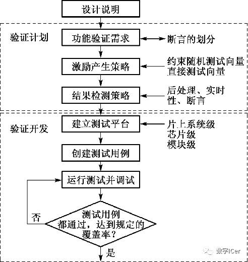
Functional Verification Development ProcessEstablishing Verification Plans
-
Functional verification requirements -
Stimulus generation strategy -
Result detection strategy
Verification Development
-
Improving verification efficiency
3. System-Level Functional Verification
3. System-Level Functional Verification
Behavioral Level Functional Verification
Testing data control flow, including initialization and shutdown of I/O devices, verifying software functionality, communication with the outside world, etc.
Performance Verification
Through performance verification, designers can clearly understand the operational speed, power consumption, and other performance metrics of the entire system.
Protocol Verification
Verification of the interface parts of each module according to the bus protocol.
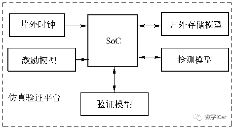
System-Level Test Platform
-
Boundary conditions -
Discontinuities in the design -
Error conditions -
Extreme cases
System-Level Test Platform Standards
-
Performance metrics -
Coverage metrics
4. Simulation Verification Automation
4. Simulation Verification Automation
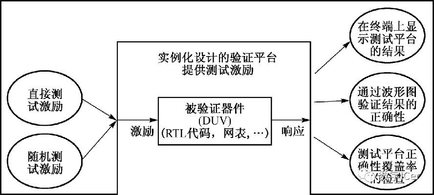
Stimulus Generation
-
Direct test stimulus: detects system defects that the tester wishes to identify
Can quickly and accurately generate a large number of input vectors that are consistent with actual applications.
-
Random test stimulus:
Detects defects in the system that the tester did not anticipate; constrained random test stimulus means applying certain constraints when generating random test vectors, ensuring that the generated random test vectors meet specific design rules.
Example of constrained random stimulus generation
x1 and x2 are two inputs to the system, which, after being encoded by a one-hot encoder, produce inputs directly connected to the design under verification (DUV).
Input constraint: in[0] + in[1] + in[2] <= 1
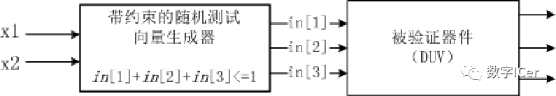
The generated random vectors can thus ensure their legality.
Example of constrained random stimulus generation written in SystemVerilog
Limit the number of input data to 1–1000
program automatic test;

// define constraint
class Transaction;
  rand  bit [31:0] src, dst, data[];  // Dynamic array
  randc bit [2:0] kind;     // Cycle through all kinds
  constraint c_len
    { data.size inside {[1:1000]}; } // Limit array size
Endclass

// instantiation
Transaction tr;

// start random vector generation
initial begin
  tr = new();
  if(!tr.randomize()) $finish;
  transmit(tr);
  end
endprogram
Response Checking
-
Visual waveform checking: Intuitive, but not suitable for complex system designs -
Automatic comparison checking: Automatically compares output results through corresponding detection models or verification models
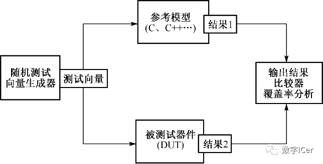
Coverage Checking
-
Coverage data is usually collected over multiple simulations. -
The coverage model consists of models defined for both structural coverage and functional coverage.
Can be refined to:
Finite State Machine (FSM) coverage, expression coverage, cross coverage, assertion coverage.
Example of coverage checking written in SystemVerilog
program automatic test(busifc.TB ifc);
  class Transaction;
     rand bit [31:0] src, dst, data;
     rand enum {MemRd, MemWr, CsrRd, CsrWr,                 I
     oRd, IoWr, Intr, Nop} kind;
  endclass

covergroup CovKind;
   coverpoint tr.kind;       // Measure coverage
endgroup

Transaction tr = new();     // Instantiate transaction
CovKind ck = new();         // Instantiate group

initial begin
   repeat (32) begin              // Run a few cycles
      if(!tr.randomize()) $finish;
      ifc.cb.kind <= tr.kind;   // transmit transaction
      ifc.cb.data <= tr.data;   //   into interface
      ck.sample();              // Gather coverage
      @ifc.cb;                  // Wait a cycle
   end
end
endprogram
5. Formal Verification
5. Formal Verification
Formal Verification
Static formal verification and semi-formal verification
-
Static formal verification does not require stimulus to be applied and does not require simulation for verification. Currently, the common static formal verification method in SoC design is equivalence checking. -
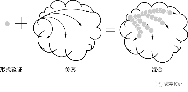
Semi-formal verification is a hybrid approach combining simulation techniques with formal verification techniques. Common semi-formal verification methods include model checking or property checking, which combine the completeness of formal verification with the speed and flexibility of simulation.
Equivalence Checking
-
Quick verification with 100% coverage of the design -
Mainly checks the functional equivalence of combinational logic -
No need for test platforms and test vectors, and no simulation is required -
Can be used to compare the functional equivalence of RTL to RTL, RTL to gate level, gate level to gate level, and is widely used for comparing extracted netlists with RTL code after layout extraction, especially for equivalence checking after completing ECO.
Semi-Formal Verification
Combining simulation and formal verification techniques, such as hybrid model checking or property checking methods.
6. Assertion-Based Verification
6. Assertion-Based Verification
Challenges in Simulation Verification: Observability and Controllability
-
Appropriate input vectors can activate errors -
Errors must be output in some expected form
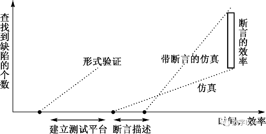
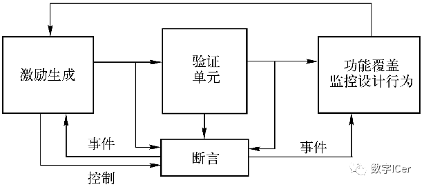
Assertions describe the behavior of the design, serving a monitoring role during simulation. When monitored properties exhibit errors, they immediately trigger error generation, enhancing the observability of the design during simulation.
Assertions can also be used in formal property checking as properties to be verified. Property checking involves searching the entire state space, allowing control over each signal and pinpointing the exact location of errors, addressing the issues of controllability and observability in design verification.
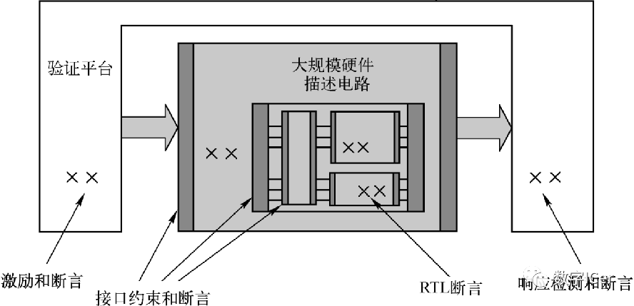
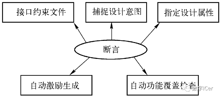
Role of Assertions
Use of Assertion Languages and Tools
Assertion Languages
C or SystemC, SystemVerilog Assertion (SVA), Property Specification Language (PSL) (IBM, based on Sugar), Open Verification Library (OVL), Verilog, VHDL
Example of SVA (SystemVerilog Assertion)
Checker implemented in Verilog:
always @ (posedge A)
begin   repeat (1) @ (posedge clk);
    fork: A_to_B
       begin @ (posedge B)
         $display ("SUCCESS: B arrived in time\n", $time);
         disable A_to_B;
       end
       begin
       repeat (1) @ (posedge clk)
         @ (posedge B)
         display ("SUCCESS: B arrived in time\n", $time);
         disable A_to_B;
       end
       begin
       repeat (2) @ (posedge clk)
         display ("ERROR: B didn’t arrive in time\n", $time);
         disable A_to_B;
       end
end
Checker implemented in SVA:
assert property
  ( @(posedge clk )A|->##[1:2]B);
Assertion-Based Verification
Using assertions in property checking
In property checking, the most important aspect is the description of the properties.
Using assertions in simulation


E-Course Network (www.eecourse.com) is a professional integrated circuit education platform under Moore Elite, dedicated to cultivating high-quality integrated circuit professionals in the semiconductor industry. The platform is oriented towards the job requirements of integrated circuit companies, providing a practical training platform that aligns with the corporate environment. Through both online and offline training methods, it quickly cultivates students to meet corporate needs.
The E-Course Network has a mature training platform, a complete curriculum system, and a strong teaching faculty, planning 168 high-quality semiconductor courses in China, covering the entire integrated circuit industry chain, and has four offline training bases. To date, a total of 15,367 individuals have been deeply trained, directly supplying 4,476 professionals to the industry. It has established deep cooperative relationships with 143 universities and has held 240 corporate-specific IC training sessions.