37 types of sensors and actuators have been widely circulated on the internet, but the number of sensor modules compatible with Arduino is certainly more than these 37 types. Given that I have accumulated some sensors and actuators, following the principle of learning through practice (it is essential to get hands-on), I am preparing to try a series of experiments one by one for the purpose of learning and communication. Regardless of whether they are successful (program runs smoothly) or not, I will record them – small progress or unresolved issues, hoping to spark ideas.
[Arduino] Series of experiments with 168 sensor modules (data code + simulation programming + graphical programming)
Experiment 109: Power Supply Module 3.3V 5V 12V Multi-Output DC-DC Voltage Converter Module
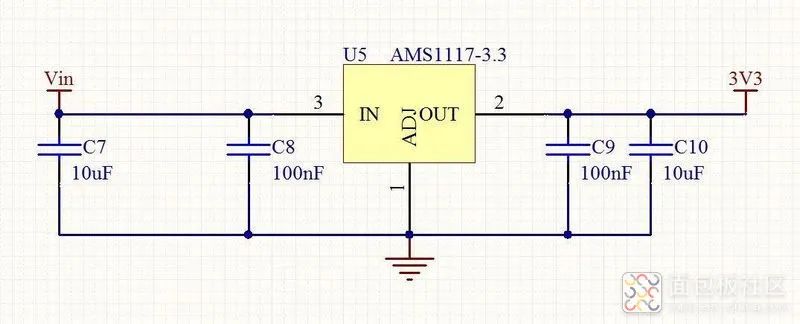
The series voltage regulators come in adjustable and various fixed voltage versions, designed to provide 1A output current with a dropout voltage as low as 1V. At maximum output current, the minimum dropout voltage for AMS1117 devices is guaranteed to be no more than 1.3V, gradually decreasing with reduced load current. The on-chip trimming of AMS1117 adjusts the reference voltage to within ±1.5% accuracy, and the current limit is also adjusted to minimize stress caused by overload on the regulator and power circuit. AMS1117 device pins are compatible with other three-terminal SCSI voltage regulators, providing suitable surface mount options in SOT-223, 8-pin SOIC, and TO-252 (DPAK) plastic packages. AMS1117 Basic Parameters
Output Voltage (V) Adj, 1.2, 1.5, 1.8, 2.5, 2.85, 3.3, 5.0, *
Package Type SOT-223 TO-252 SO-8
Three-terminal adjustable or fixed output voltages of 1.2V, 1.5V, 1.8V, 2.5V, 2.85V, 3.3V, and 5.0V with an output current of 1A and a working dropout as low as 1V. Line load regulation: 0.2% Max. Load regulation: 0.4% Max. Available in SOT-223, TO-252, and SO-8 packages.
 is a device that converts electrical energy from one voltage level to another in a DC circuit. It employs microelectronics technology to integrate small surface-mounted integrated circuits with miniature electronic components. The DC-DC is a newly developed miniaturized power switch module, which utilizes microelectronics technology to assemble small surface-mounted integrated circuits with miniature electronic components into one unit. The use of DC-DC power modules helps simplify power circuit design, shorten development cycles, and achieve optimal specifications, making them widely applicable in various digital instruments and smart devices. DC-DC power modules are widely used in power electronics, military industry, scientific research, industrial control equipment, communication devices, instruments, switching equipment, access devices, mobile communications, routers, and other fields of communication and industrial control, automotive electronics, and aerospace. The modular construction of power systems has characteristics such as short design cycles, high reliability, and easy system upgrades, making the application of power modules increasingly widespread. Especially in recent years, due to the rapid development of data services and the continuous promotion of distributed power supply systems, the growth of power modules has exceeded that of primary power supplies. With the extensive use of semiconductor processes, packaging technology, and high-frequency soft switching, the power density of power modules has increased, conversion efficiency has improved, and applications have become simpler.
 is a voltage converter that effectively outputs a fixed voltage after changing the input voltage. DC/DC converters are divided into three types: boost DC/DC converters, buck DC/DC converters, and buck-boost DC/DC converters. Depending on the requirements, any of the three types can be used. The PWM control type is efficient and has good output voltage ripple and noise. The PFM control type has the advantage of low power consumption even during prolonged use, especially under light load. The PWM/PFM converter implements PFM control under light load and automatically switches to PWM control under heavy load. Currently, DC-DC converters are widely used in products such as mobile phones, MP3 players, digital cameras, and portable media players. In terms of circuit type classification, it belongs to the chopping circuit.
Working Principle of DC-DC Converter
What is DC (Direct Current)? It refers to direct current power sources, such as dry batteries or car batteries. The household 220V power supply is an alternating current (AC) source. If a converter can convert a direct current voltage (3.0V) into another direct current voltage (1.5V or 5.0V), we call this converter a DC-DC converter, or a switching power supply or switching regulator.
A: DC-DC converters are generally composed of control chips, inductors, diodes, transistors, and capacitors. When discussing the performance of a DC-DC converter, it is not sufficient to judge solely based on the control chip. The characteristics of the components in the peripheral circuit and the layout of the circuit board can affect the performance of the power circuit, so a comprehensive evaluation should be conducted.
1: PFM (Pulse Frequency Modulation)
The switch pulse width is fixed, and by changing the frequency of the pulse output, the output voltage is stabilized.
2: PWM (Pulse Width Modulation)
The frequency of the switching pulse is fixed, and by changing the output pulse width, the output voltage is stabilized.
C: Generally, the performance differences between DC-DC converters using PFM and PWM modulation methods are as follows.
PWM frequency and PFM duty cycle selection methods.
Switching voltage regulator chip solutions: wide voltage regulation range, low energy loss, simply put, it releases energy as needed.
Functions of DC-DC Converter
1. Noise Isolation: (isolation of analog circuits from digital circuits, isolation of strong and weak signals)
2. Safety Isolation: isolation of high voltage from low voltage, IGBT isolation drive, surge isolation protection, lightning isolation protection (such as isolation protection for medical electronic devices that contact the human body)
3. Ground Loop Elimination: remote signal transmission, distributed power supply systems
Boost conversion, buck conversion, AC/DC conversion, DC/AC conversion, polarity conversion (positive-negative polarity conversion, single power supply and positive-negative power supply conversion, single power supply and multiple power supplies conversion)
Short circuit protection, overvoltage protection, undervoltage protection, overcurrent protection, other protections
Powered by AC mains, remote DC supply, distributed power supply systems, battery power supply
1. The voltage at the input and output terminals is smooth direct current, with no AC harmonic components
2. Output impedance is zero
3. Fast dynamic response, strong suppression capability
4. High efficiency and miniaturization
1. Driving: Electric vehicles, subways, electric cars, trains
2. DC motor speed control systems,
3. Lighting, xenon lamp ballast
4. Switching power supply, e.g., Adapter, VRM
Two voltage regulator chips AMS1117 on the module
3.3V 5V 12V multi-output power module
1 One input: DC 6V–12V (the input voltage must be more than 1V higher than the output voltage).
2 Three outputs: 3.3V (±0.05V error), 5.0V (±0.05V error), 800mA (load current must not exceed 800mA), 12V (direct conversion from input 12V)
3 Double-sided board design, beautiful and generous layout;
4 Specially designed with 2 fixing holes for pin headers, can be directly fixed on the perforated board for expansion experiments;
5 Multiple pin headers for input and output, convenient for use and connection;
7 With power indicator light (red)
[Arduino] Series of experiments with 168 sensor modules (data code + simulation programming + graphical programming)
Experiment 109: Power Supply Module 3.3V 5V 12V Multi-Output DC-DC Voltage Converter Module
Project: Detecting the three output voltage values of the power supply module
is a voltage converter that effectively outputs a fixed voltage after changing the input voltage. DC/DC converters are divided into three types: boost DC/DC converters, buck DC/DC converters, and buck-boost DC/DC converters. Depending on the requirements, any of the three types can be used. The PWM control type is efficient and has good output voltage ripple and noise. The PFM control type has the advantage of low power consumption even during prolonged use, especially under light load. The PWM/PFM converter implements PFM control under light load and automatically switches to PWM control under heavy load. Currently, DC-DC converters are widely used in products such as mobile phones, MP3 players, digital cameras, and portable media players. In terms of circuit type classification, it belongs to the chopping circuit.
Working Principle of DC-DC Converter
What is DC (Direct Current)? It refers to direct current power sources, such as dry batteries or car batteries. The household 220V power supply is an alternating current (AC) source. If a converter can convert a direct current voltage (3.0V) into another direct current voltage (1.5V or 5.0V), we call this converter a DC-DC converter, or a switching power supply or switching regulator.
A: DC-DC converters are generally composed of control chips, inductors, diodes, transistors, and capacitors. When discussing the performance of a DC-DC converter, it is not sufficient to judge solely based on the control chip. The characteristics of the components in the peripheral circuit and the layout of the circuit board can affect the performance of the power circuit, so a comprehensive evaluation should be conducted.
1: PFM (Pulse Frequency Modulation)
The switch pulse width is fixed, and by changing the frequency of the pulse output, the output voltage is stabilized.
2: PWM (Pulse Width Modulation)
The frequency of the switching pulse is fixed, and by changing the output pulse width, the output voltage is stabilized.
C: Generally, the performance differences between DC-DC converters using PFM and PWM modulation methods are as follows.
PWM frequency and PFM duty cycle selection methods.
Switching voltage regulator chip solutions: wide voltage regulation range, low energy loss, simply put, it releases energy as needed.
Functions of DC-DC Converter
1. Noise Isolation: (isolation of analog circuits from digital circuits, isolation of strong and weak signals)
2. Safety Isolation: isolation of high voltage from low voltage, IGBT isolation drive, surge isolation protection, lightning isolation protection (such as isolation protection for medical electronic devices that contact the human body)
3. Ground Loop Elimination: remote signal transmission, distributed power supply systems
Boost conversion, buck conversion, AC/DC conversion, DC/AC conversion, polarity conversion (positive-negative polarity conversion, single power supply and positive-negative power supply conversion, single power supply and multiple power supplies conversion)
Short circuit protection, overvoltage protection, undervoltage protection, overcurrent protection, other protections
Powered by AC mains, remote DC supply, distributed power supply systems, battery power supply
1. The voltage at the input and output terminals is smooth direct current, with no AC harmonic components
2. Output impedance is zero
3. Fast dynamic response, strong suppression capability
4. High efficiency and miniaturization
1. Driving: Electric vehicles, subways, electric cars, trains
2. DC motor speed control systems,
3. Lighting, xenon lamp ballast
4. Switching power supply, e.g., Adapter, VRM
Two voltage regulator chips AMS1117 on the module
3.3V 5V 12V multi-output power module
1 One input: DC 6V–12V (the input voltage must be more than 1V higher than the output voltage).
2 Three outputs: 3.3V (±0.05V error), 5.0V (±0.05V error), 800mA (load current must not exceed 800mA), 12V (direct conversion from input 12V)
3 Double-sided board design, beautiful and generous layout;
4 Specially designed with 2 fixing holes for pin headers, can be directly fixed on the perforated board for expansion experiments;
5 Multiple pin headers for input and output, convenient for use and connection;
7 With power indicator light (red)
[Arduino] Series of experiments with 168 sensor modules (data code + simulation programming + graphical programming)
Experiment 109: Power Supply Module 3.3V 5V 12V Multi-Output DC-DC Voltage Converter Module
Project: Detecting the three output voltage values of the power supply module
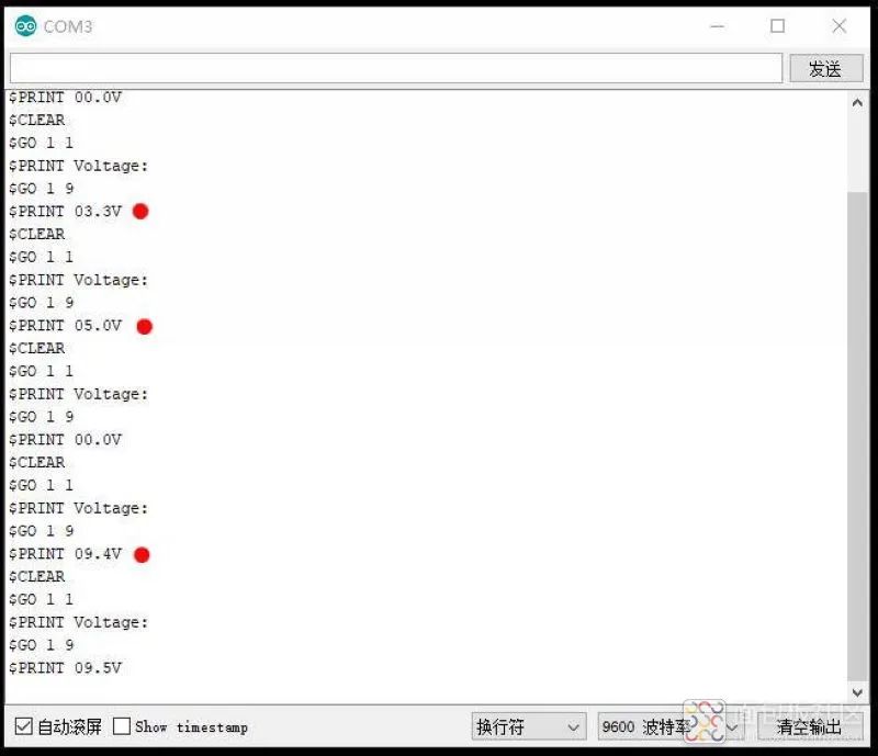
/*[Arduino] Series of experiments with 168 sensor modules (data code + simulation programming + graphical programming) Experiment 109: Power Supply Module 3.3V 5V 12V Multi-Output DC-DC Voltage Converter Module Project: Detecting the three output voltage values of the power supply module 5V---------VCC GND--------GND A0------S (output port)*/ int analogpin=0; int val,val5; int val2=0; int val3=0; int val4=0; void setup(){ Serial.begin(9600); } void loop(){ int val,val5; float val1; val=analogRead(analogpin); val1=val/4.2; val5=(int)val1; val3=val5/100; val2=(val5%100)/10; val4=val5%10; Serial.print("$CLEAR\r\n"); Serial.print("$GO 1 1\r\n"); Serial.print("$PRINT Voltage:\r\n"); Serial.print("$GO 1 9\r\n"); Serial.print("$PRINT "); Serial.print(val3); Serial.print(val2); Serial.print("."); Serial.print(val4); Serial.println("V"); delay(5000); }
Experiment serial port return situation
Open-source graphical programming (Mind+, Learn while playing)

Experiment serial port return situation

Experiment scene image

Author: Diao Ye Learning Programming, Source: Breadboard Community
Link: https://mbb.eet-china.com/blog/3894459-437232.html
Copyright Statement: This article is original by the author, and reproduction is prohibited without permission!
[Share Circuits] Good Circuit Books! Everyone has red envelopes to grab!
You can share the content:
1. The circuit schematic you designed
2. Explanation and analysis of the circuit diagram you designed
3. Discussion on design ideas, circuit analysis, applications, optimizations, questions, etc.
Activity Prizes:
First Prize: 300 Yuan JD E-card
Several Excellent Prizes: 50 Yuan JD E-card
Participation rewards of 20 Yuan JD E-card!
Excellent participants randomly receive “Good Circuit Books”!
To participate in the activity, please click here