You can directly obtain the engineering files at the Lichuang Open Source Square.
https://oshwhub.com/zctnb/works
Actually, the chips are the same, but the ESP32C3WROOM is a module, while the ESP32C3FH4 is a chip that integrates 4MB of flash.
Let me explain for those who are not quite clear.
The image below is a screenshot from the official manual of Espressif.
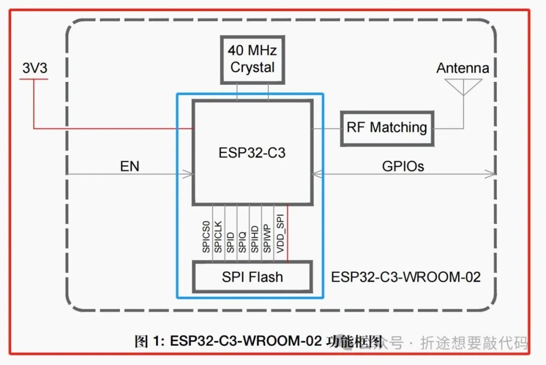
The red box outlines the ESP32C3WROOM module, while the blue box outlines the ESP32C3FH4 chip.
The difference between them is the 40MHz crystal oscillator and the antenna; the ESP32C3WROOM has an onboard antenna.
If we are using the ESP32C3 chip, we still need to add the flash ourselves.
In summary, the module is more convenient; we only need to add a few capacitors and resistors externally to make it work, while using the chip requires us to handle the crystal oscillator, antenna (flash), and so on.
However, the module is obviously more expensive. If we buy the chip, even adding the crystal oscillator and ceramic antenna (if you’re skilled enough, you can design an onboard antenna) will be cheaper than buying the module.
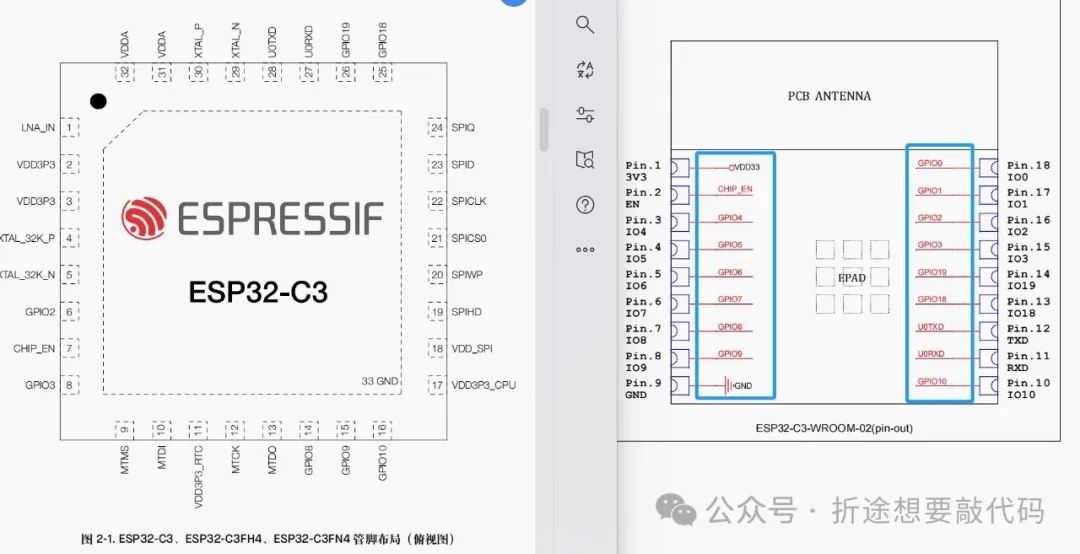
Moreover, the module has fewer pins, while using the chip gives us more available pins; IO11~IO16 are not brought out by the module. If our project requires more pins, it’s better to use the chip, as the module might not have enough pins.
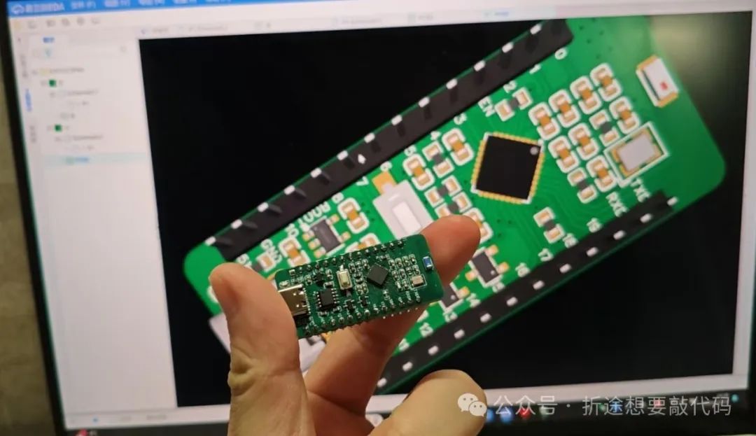
Therefore, today I’m open-sourcing the ESP32C3FH4 core board.
It’s actually quite similar to the module; you can refer to my previous article.
Open Source ESP32-C3-WROOM Core Board Design
Since most of it is similar, we will only discuss the differences, which are the antenna and crystal oscillator.
We can refer to Espressif’s official hardware design guidelines.
https://docs.espressif.com/projects/esp-hardware-design-guidelines/zh_CN/latest/esp32c3/schematic-checklist.html
First is the crystal oscillator.
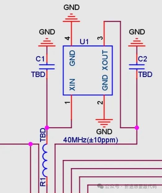
The requirement is a 40MHz crystal oscillator, then two capacitors and an inductor in series.
The value of the inductor varies with the PCB; the initial value is 24nH, so we can just use 24nH.
For the capacitors on both sides of the crystal, generally, when the capacitors on both ends are equal, there is a formula:
Load capacitance of the crystal = (Capacitance on both ends / 2) + PCB parasitic capacitance + Static capacitance of the crystal.
The load capacitance and static capacitance of the crystal can be found in the crystal’s manual, and the PCB parasitic capacitance is generally taken as 5pf.
For the crystal I used as an example.
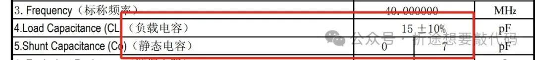
Load capacitance is 15pf, static capacitance is 0~7pf, we take 3.5.
Calculating gives us the capacitance values on both ends as 13pf.
If you use a different crystal, remember to adjust the capacitance values according to the parameters to increase stability.
Next is the antenna.
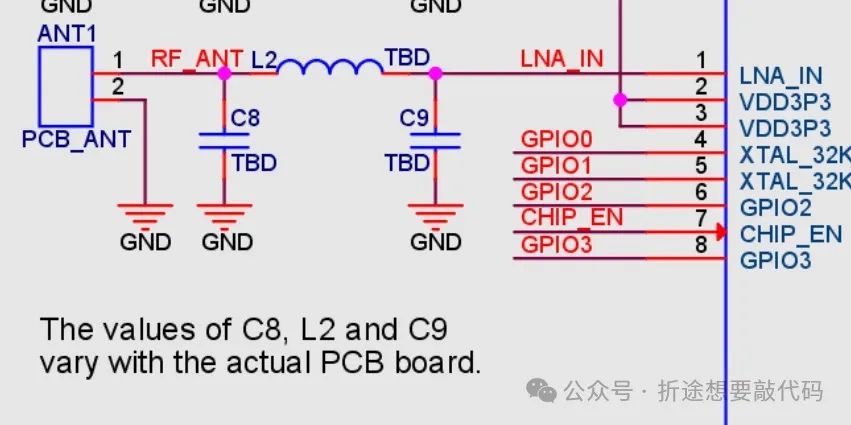
It requires two capacitors and an inductor, with values varying with the PCB.
This is a π-type impedance matching circuit.
I gave 100nf (should be a bit smaller), and the inductor was changed to 0Ω. I forgot who I borrowed this from; today while writing this article, I checked the information again, and it seems that the capacitance values for the antenna matching circuit are all in the pf range…
However, through my experiments, the antenna works normally; at least when I burned the WiFi and Bluetooth codes, they ran fine.
Anyway, there should be pads left for the π-type circuit on the antenna side. If the RF requirements are quite high, you may need to debug it yourself. I’m not very familiar with this area; I’ve seen others just solder a 0Ω resistor and it works.
That’s all I have to say about circuit design; the other parts are the same as the ESP32C3WROOM. For details, you can refer to my previous article, which is very detailed in conjunction with the manual, so I won’t repeat it here.
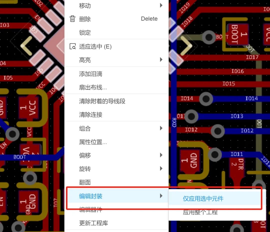
The last issue is soldering. QFN packages are really super hard to solder. If you have hot air or a heated plate, that’s fine; if not, it’s difficult. I can’t use this high-power hot air in my dorm, so I had to solder it with a soldering iron, and I had to re-solder it two or three times before it worked. This was after I extended the pads of the package; otherwise, the soldering iron wouldn’t be able to solder it at all.
For those who are not good at soldering, you can extend the pads a bit more.
Right-click on ESP32C3FH4, select edit package, and modify it; just don’t make it too long.
That’s all for this article.
Regarding the use of ESP-IDF, I have also completed a series of articles, which are updated in the ESP32 collection; interested friends can check them out.