This article introduces how to perform automated testing on embedded software within various controllers and recommends a tool that supports comprehensive automated testing of embedded software. This tool supports CAN communication testing, LIN communication testing, Ethernet communication testing, various sensor simulation testing, and supports automated testing for various embedded systems developed based on MCU, SOC, DSP, FPGA, etc., which can comprehensively cover various timing logic and business functions of embedded systems. Currently, this tool supports applications for free trials (please see how to apply for a trial at the end of the article).
Embedded systems for controllers (including ECU and domain controllers) generally have multiple input and output interfaces, such as IO signal interfaces, analog signal interfaces, I2C communication interfaces, SPI communication interfaces, CAN communication interfaces, Ethernet communication interfaces, wireless communication interfaces, etc. The controller needs to respond in real-time to these interfaces and execute various complex timing logic. How can such embedded systems be thoroughly tested? How can various normal and abnormal testing scenarios be covered?
The Macrocontrol UTP Collaborative Automated Testing System (hereinafter referred to as the UTP testing system) is a general-purpose automated testing system that supports full simulation and partial simulation environment testing, supports SIL and HIL testing, and supports automated simulation and testing for bus communication, signal detection, sensor simulation, wireless communication, human-computer interaction, etc. At the same time, the UTP testing system supports users to customize various timing logic, supports automated testing of various complex timings, and supports anomaly injection; the UTP testing system also provides comprehensive automated testing management functions, supporting comprehensive management of the entire testing work.
Functions of the UTP testing system:
-
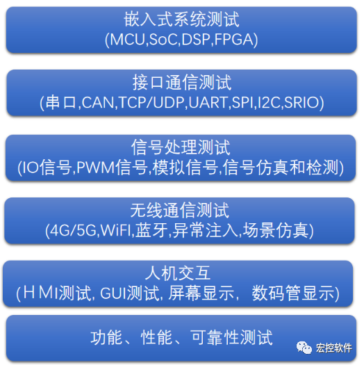
Supports interface bus communication testing: supports various bus communication tests, such as CAN, LIN, FlexRay, CANFD communication, RS232/RS485/RS422 communication, Ethernet communication (TCP/UDP protocol, DoIP protocol, SOME/IP protocol, DDS protocol, etc.), I2C communication, SPI communication, etc.
-
Supports wireless communication simulation testing: supports simulation testing of various wireless communications, such as 4G/5G, Bluetooth, WIFI, GPS, Beidou, etc. No reliance on real wireless environments is needed, and comprehensive automated testing of business can be achieved through simulation, supporting simulation of various abnormal scenarios.
-
Supports signal simulation and testing: supports testing of various IO signals, PWM signals, analog signals, supports automatic sensor signal simulation testing, and supports automatic detection and judgment of various signals output by the tested system.
-
Supports UI display recognition and testing: supports recognition, detection, and automatic judgment of displays of various embedded system UIs (such as screens and digital tubes), supports testing of various desktop software and embedded software GUIs (such as Qt software testing).
Example Solution for Embedded Automated Testing
Below, we take the automated testing solution for the motor control module in a certain motor controller as an example to analyze how to use the Macrocontrol UTP testing system to establish an automated testing environment for the tested embedded system.
(1) Composition of the tested system
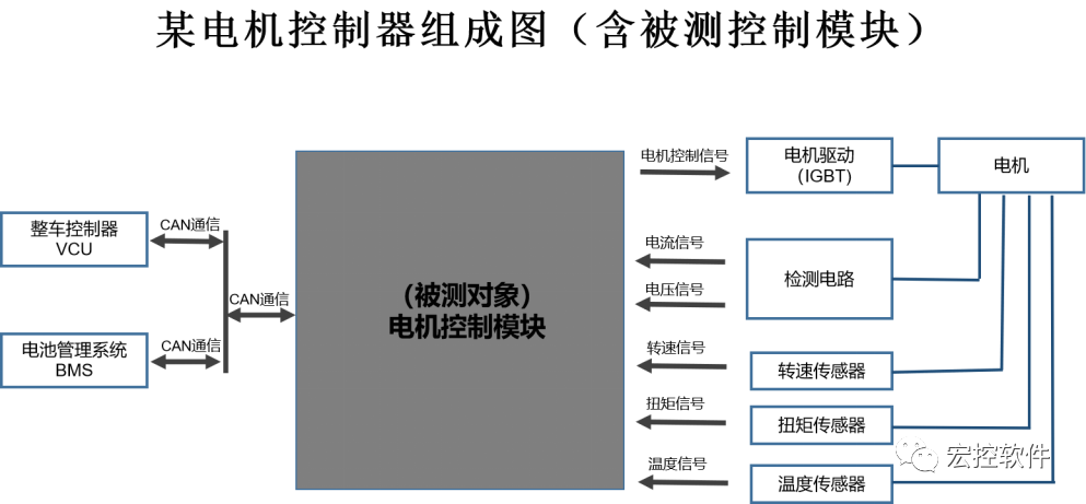
The motor control module is the core module of the motor controller. The motor control module communicates with the vehicle control unit (VCU) and the battery management system (BMS) through the CAN interface, receiving control information such as target speed and torque sent by the VCU, controlling the motor’s motion through PWM signals, real-time collecting and processing various sensor signals (such as speed, torque, temperature, etc.), and sending current speed and other information to the vehicle control unit (VCU).
(2) A typical working sequence of the tested system
① The motor control module receives speed and torque signals sent by the vehicle control unit through the CAN interface
② The motor control module outputs PWM motor control signals to the IGBT
③ The motor control module detects current, voltage, speed, torque, and temperature signals
④ The motor control module sends the current speed and torque to the vehicle control unit via the CAN interface
(3) Establishing an automated simulation environment
The following figure shows that the Macrocontrol UTP testing system provides a full simulation testing environment for the tested motor control module.
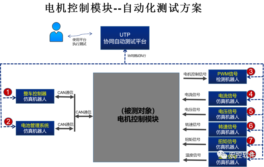
As shown in the figure above, the UTP testing system establishes a fully simulated automated testing environment for the motor control module. Users can conduct various timing and control logic tests on the tested motor control module through the UTP collaborative testing platform, comprehensively validating various normal and abnormal scenarios.
The UTP testing system realizes different simulation and detection functions through various automated testing robots. These automated testing robots include:
① Vehicle control unit simulation robot: Automatically simulates the vehicle control unit to communicate with the motor control module via CAN
② Battery management system simulation robot: Automatically simulates the battery management system to communicate with the motor control module via CAN
③ PWM signal detection robot: Automatically detects the PWM control signals emitted by the motor control module
④ Current signal simulation robot: Automatically simulates the current signal feedback from the motor
⑤ Power signal simulation robot: Automatically simulates the voltage signal feedback from the motor
⑥ Speed signal simulation robot: Automatically simulates the speed signal feedback from the motor
⑦ Torque signal simulation robot: Automatically simulates the torque signal feedback from the motor
⑧ Temperature signal simulation robot: Automatically simulates the temperature signal feedback from the motor
(4) Designing automated simulation testing timing
Various testing timing logic can be written on the UTP system. The UTP system will schedule the testing robots to execute collaboratively according to the timing logic, achieving comprehensive automated testing of the tested motor control module. Below is an automated testing case created on the UTP system (corresponding to a testing timing logic of the above working sequence).
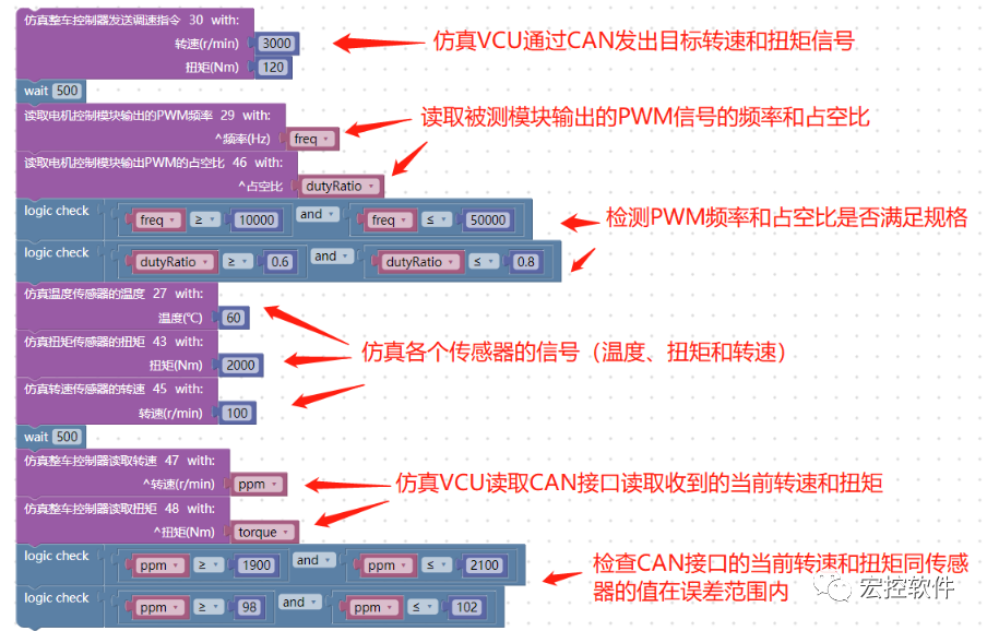
Using the Macrocontrol UTP collaborative automated testing system, various testing timings can be written, and the written testing logic can be executed automatically, conveniently achieving full coverage testing of various abnormal and normal scenarios.
Usage Method of the UTP System Embedded Automated Testing
The UTP automated testing system consists of the UTP testing platform and the testing robot box (which contains various automated testing robots). The specific usage method of the UTP system is introduced below.
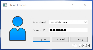
(1) Start and log in to the testing robot box
The testing robot box runs various testing robots (such as CAN testing robots, Ethernet testing robots, IO signal testing robots, etc.), and these testing robots will connect the tested embedded system through hardware modules.
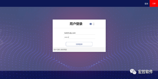
(2) Log in to the UTP testing platform
Enter the account and password to log in to the UTP platform, supporting simultaneous login by multiple users.
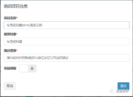
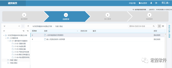
(3) Create a testing project
Enter the project name, tested object name, and project description information, click to create the project, and support the creation of multiple testing projects (corresponding to different product projects). Here, a project is created for testing the body controller as an example.
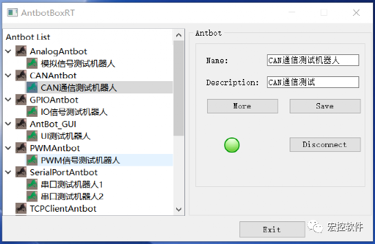
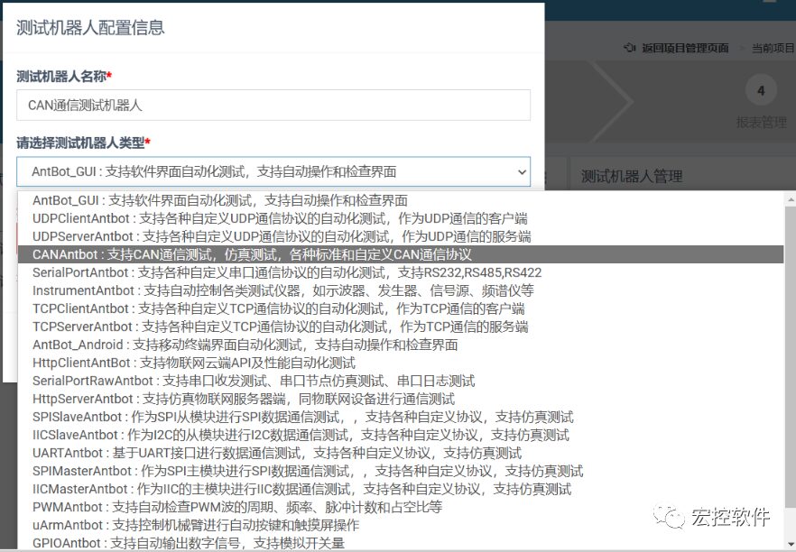
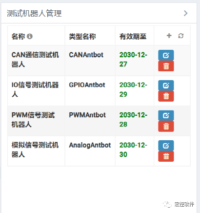
(4) Configure the testing robots used in the project
According to the actual project usage needs, configure one or more testing robots. The following figure configures the CAN communication testing robot, IO signal testing robot, PWM signal testing robot, and analog signal testing robot.
(5) Design automated testing use cases
Users can design various testing use cases for timing logic and business scenarios without writing code, supporting graphical block-style creation of various testing use cases, and supporting users to design any number of testing use cases:
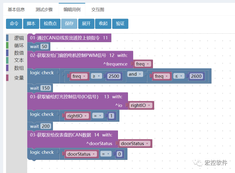
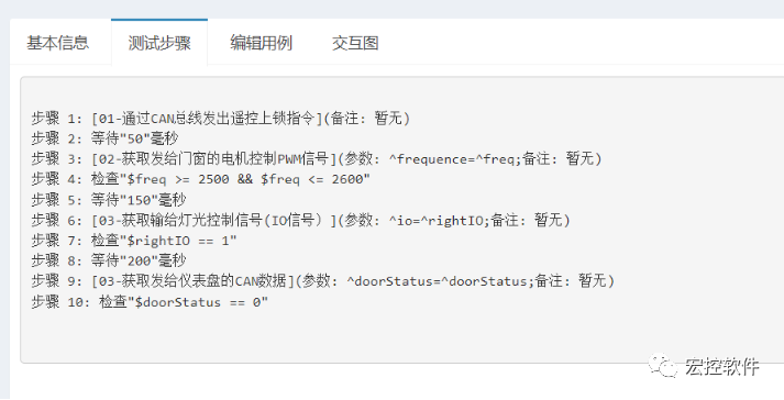
The designed use cases automatically generate testing steps. The following figure shows the testing steps corresponding to the above testing timing:
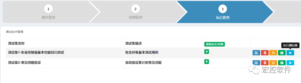
(6) Execute the test set
Supports selecting a set of testing use cases to create a test set, supports one-click execution of multiple selected testing use cases through the test set, used for automated regression testing. The following figure creates two test sets, which can perform one-click automated regression testing separately.
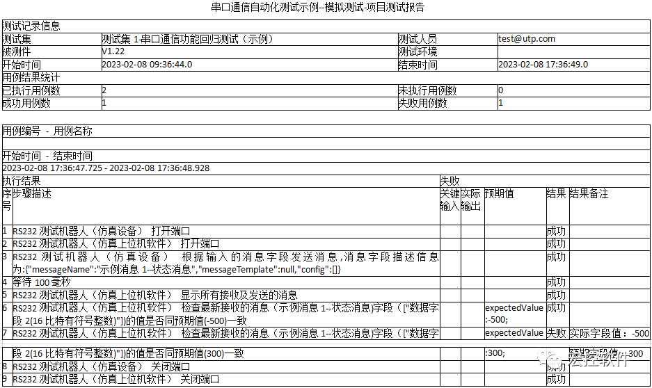
(7) View the test report
The UTP testing system automatically generates test reports, supports exporting test reports (in Word file format), and the reports include statistics on executed use cases and detailed results of each use case execution. For example, the automatically marked failure steps and reasons in the test report facilitate quick problem localization.
Features of the Macrocontrol UTP Embedded Testing System
Supports flexible selection of various testing functions
The following functions support selection based on actual project needs:
-
Bus testing functions: CAN, LIN, FlexRay, CANFD, RS232, RS485, RS422, Ethernet, I2C, SPI, etc.
-
Signal testing functions: IO signals, PWM signals, analog signals
-
Wireless testing functions: 4G/5G, Bluetooth, WiFi, navigation (GPS, Beidou)
-
UI testing functions: various software UIs, embedded system UIs
No programming required, supports testing of various complex scenarios
-
Supports graphical design of various testing use cases without programming in C/C++ or other languages
-
Supports rapid design of various complex timing logics, supports anomaly injection, supports scenario simulation
Provides full-process automated testing management
-
Unified management of various testing documents, testing scripts, and testing tools;
-
Supports product traceability matrix, supports testing requirements, testing cases, and testing results management
-
Supports team sharing of various testing resources
Macrocontrol UTP Embedded Testing System Can Help You
Supports rapid establishment of various automated testing environments
-
Supports testing of various embedded systems, bus communication testing, signal simulation testing
-
Supports hardware-in-the-loop (HIL) and software-in-the-loop (SIL) testing
-
Supports building semi-physical semi-simulation environments and full simulation testing environments
Supports rapid product iteration, continuously ensuring product reliability
-
Supports establishing comprehensive automated testing use cases to test various functions, performance, and reliability of products
-
Automated regression testing during product changes, continuously ensuring the reliability and stability of the tested products
Improves testing efficiency, reduces testing costs
-
Unified management of various testing documents, testing scripts, and testing tools;
-
Manual testing that takes weeks can be completed in a few hours with automated testing
-
Functions that are difficult to test manually can be easily tested with automation
More Introductions
The detailed introduction of the Macrocontrol UTP testing system can be viewed on the company’s official website:
Company website:https://www.macrosoftsys.com
UTP online version (free trial):https://www.antestin.com (log in on a computer)
You can also join the following automated testing group for discussion and exchange of related automated testing technologies:

Free Trial Application
The Macrocontrol UTP automated testing system now supports free trial applications:
The Macrocontrol UTP automated testing kit (trial version), including trial software and hardware, supports bus communication testing, signal simulation testing, wireless communication simulation, and other automated modules, supporting testing of various ECUs and domain controllers.
This trial kit includes:
(1) Interface bus communication automated testing
-
Supports CAN, LIN, RS232/485/422, Ethernet, I2C, SPI, and other buses
-
Supports testing of various standard communication protocols and custom protocols
-
Compatible with CANoe protocol file format (dbc files)
-
Supports various business communication, diagnostics, simulation, and other functions
(2) Automated signal simulation and signal detection
-
Supports testing of IO signals, PWM signals, and analog signals
-
Supports multi-channel signal input and output
-
Supports simulation testing of various sensors
(3) Automated wireless communication testing
-
Supports simulation testing of 4G/5G, Bluetooth, navigation signals
-
Supports simulating various abnormal communication scenarios
-
Supports OTA upgrade testing
(4) Automated simulation testing
-
Supports simulating various actual environmental parameters, such as temperature, pressure, altitude, speed, etc.
-
Supports flexible configuration of simulation parameters
-
Supports simulation of signals, timing, algorithms, scenarios, etc.
Trial application: Please add the following WeChat and note “UTP Embedded Testing Kit Trial Application”

Macrocontrol Software Introduction
Macrocontrol Software is a company that provides professional automation testing tools and solutions for software and hardware products across various industries, offering various automation testing tools, including embedded software testing, bus communication testing, wireless communication testing, desktop software testing, etc., helping customers establish automated testing environments, discover deep-seated issues in products, improve product reliability, and reduce product development and testing costs.
For more introduction information, please visit the company’s official website:https://www.macrosoftsys.com