1. Common Electrical Symbols Drawing Methods
1. Several Basic Concepts:
Contact: The dynamic contact point of the electrical device, also known as the contact head.
Make: This describes the action of the contact point, closing (connecting) when energized, also known as normally open; a make contact is also called a normally open contact.
Break: This describes the action of the contact point, opening when energized, also known as normally closed; a break contact is also called a normally closed contact.
Coil: A winding used to generate a magnetic field force through current in the energized state, driving the action mechanism of the electrical device.
2. Common Electrical Symbol Table
The following table is essential to master and must be memorized to correctly understand the drawings.
For a more detailed symbol table, refer to GB4728.
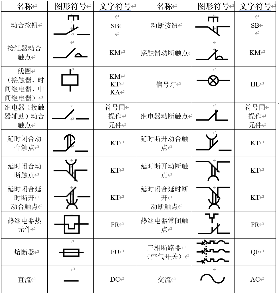
National Standard Symbol Table
(Continuation of National Standard Symbol Table)
Note the drawing method of contacts: they are all left open and right closed or up open and down closed.
2. Common Electrical Symbol Identification
The table below shows the symbol representation for various components (including semiconductor elements), with the more common ones highlighted in red background.
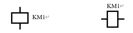
Character symbols are textual markings next to the circuit graphic symbols used for device numbering.
For example:
Figure 5-1: Graphic Symbols and Character Symbols
Numbers are generally given in Arabic numerals.
|
Device, Equipment, and Component Types |
Examples |
Basic Character Symbol |
IEC |
|
|
Chinese Name |
English Name |
Single Letter |
Double Letter |
|
|
Component Part |
Discrete component amplifier |
Amplifier using discrete |
A |
= |
|
Components |
||||
|
Laser |
Laser |
|||
|
Regulator |
Regulator |
|||
|
Other components not mentioned elsewhere in this table |
||||
|
Bridge |
Bridge |
AB |
||
|
Transistor amplifier |
Transistor amplifier |
AD |
= |
|
|
Integrated circuit amplifier |
Integrated circuit amplifier |
AJ |
= |
|
|
Magnetic amplifier |
Magnetic amplifier |
AM |
= |
|
|
Valve amplifier |
Valve amplifier |
AV |
= |
|
|
Printed circuit board |
Printed circuit board |
AP |
= |
|
|
Drawer |
Drawer |
AT |
= |
|
|
Rack |
Rack |
AR |
= |
|
|
Thermoelectric sensor |
Thermoelectric sensor |
B |
= |
|
|
Thermo-cell |
Thermo-cell |
|||
|
Photoelectric cell |
Photoelectric cell |
|||
|
Dynamometer |
Dynamometer |
|||
|
Crystal transducer |
Crystal transducer |
|||
|
Microphone |
Microphone |
|||
|
Pick up |
Pick up |
|||
|
Loudspeaker |
Loudspeaker |
|||
|
Earphone |
Earphone |
|||
|
Synchro |
Synchro |
|||
|
Resolver |
Resolver |
|||
|
Analogue and multiple-step digital transducers or sensors (as used indicating measuring purposes) |
Analogue and multiple-step digital transducers or sensors (as used indicating measuring purposes) |
|||
|
Pressure transducer |
Pressure transducer |
BP |
= |
|
|
Position transducer |
Position transducer |
BQ |
= |
|
|
Rotation transducer (tacho generator) |
Rotation transducer (tacho generator) |
BR |
= |
|
|
Temperature transducer |
Temperature transducer |
BT |
= |
|
|
Velocity transducer |
Velocity transducer |
BV |
= |
|
|
Capacitor |
Capacitor |
C |
= |
|
Device, Equipment, and Component Types |
Examples |
Basic Character Symbol |
IEC |
|
Chinese Name |
English Name |
Single Letter |
Double Letter |
|
Binary components Delay devices Storage devices |
Digital integrated circuits and devices: |
D |
= |
|
Delay line |
Delay line |
||
|
Bistable element |
Bistable element |
||
|
Monostable element |
Monostable element |
||
|
Other components |
Devices not specified elsewhere in this table |
E |
= |
|
Heating device |
Heating device |
EH |
= |
|
Lamp for lighting |
Lamp for lighting |
EL |
= |
|
Ventilator |
Ventilator |
EV |
= |
|
Over voltage discharge device Arrester |
Over voltage discharge device Arrester |
F |
= |
|
Current threshold protective device with Instantaneous action |
Current threshold protective device with Instantaneous action |
FA |
= |
|
Current threshold protective device with Time-lag action |
Current threshold protective device with Time-lag action |
FR |
= |
|
Current threshold protective device with Instantaneous and time-lag action |
Current threshold protective device with Instantaneous and time-lag action |
FS |
= |
|
Fuse |
Fuse |
FU |
= |
|
Voltage threshold protective device |
Voltage threshold protective device |
FV |
= |
|
Generator Power supply |
Rotating generator Oscillator |
G |
= |
|
Generator |
Generator |
GS |
= |
|
Synchronous generator |
Synchronous generator |
|
Device, Equipment, and Component Types |
Examples |
Basic Character Symbol |
IEC |
|
Chinese Name |
English Name |
Single Letter |
Double Letter |
|
Modulator Converter |
Inverter |
U |
= |
|
Rectifier |
Rectifier |
||
|
Telegraph translator |
Telegraph translator |
||
|
Gas-discharge tube Diode Transistor Thyristor |
Gas-discharge tube Diode Transistor Thyristor |
V |
= |
|
Electronic tube |
Electronic tube |
VE |
|
|
Rectifier for control circuit supply |
Rectifier for control circuit supply |
VC |
= |
|
Transmission channel Waveguide Antennas |
Conductors Cables Busbars Waveguide |
W |
= |
|
Waveguide directional coupler |
Waveguide directional coupler |
||
|
Dipole Parabolic antenna |
Dipole Parabolic antenna |
||
|
Terminals Plugs Sockets |
Connecting plugs and sockets Terminal Cable sealing ends and joints Soldering terminal strips |
X |
= |
|
Link |
Link |
XB |
= |
|
Test jack |
Test jack |
XJ |
= |
|
Plug |
Plug |
XP |
= |
|
Socket |
Socket |
XS |
= |
|
Pneumatic valve |
Pneumatic valve |
Y |
= |
|
Electromagnet |
Electromagnet |
YA |
= |
|
Electromagnetically operated brake |
Electromagnetically operated brake |
YB |
= |
|
Electromagnetically operated clutch |
Electromagnetically operated clutch |
YC |
= |
|
Magnetic chuck |
Magnetic chuck |
YH |
= |
|
Motor operated valve |
Motor operated valve |
YM |
= |
|
Electromagnetically operated valve |
Electromagnetically operated valve |
YV |
= |
|
Terminal device |
Cable balancing network |
Z |
= |
|
Hybrid transformer |
Compression expander |
Compandor |
|
|
Filter |
Crystal filter |
Crystal filter |
|
|
Equalizer |
Equalizer |
||
|
Limiter |
Network |
Network |
3. Typical Relay Unit Circuits
It is essential to be able to draw the following circuits proficiently.
1. Start/Stop Circuit
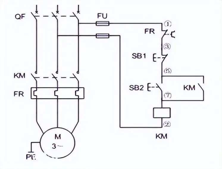
Figure 5-2: Start Stop Circuit
The coil KM is powered through button SB2, and the auxiliary contact of contactor KM closes, continuously supplying power to the coil. At this time, even if the start button SB2 is released, the coil KM continues to be powered, unless it is interrupted once by button SB1, at which point the KM coil loses power. Here, SB2 is the start button, and SB1 is the stop button.
2. Forward/Reverse Circuit
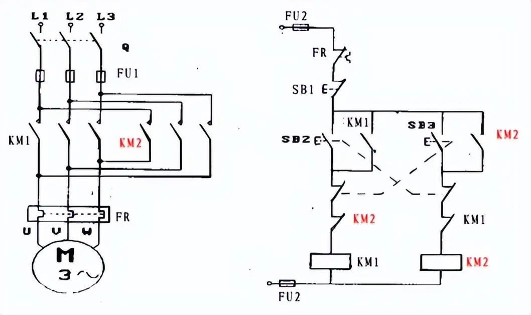
Figure 5-3: Forward Reverse Circuit
SB2 and SB3 are used to start the forward and reverse contactors KM1 and KM2, respectively, while the forward and reverse contactors self-lock and interlock through their own auxiliary contacts. The interlock control is also achieved through buttons SB2 and SB3. FR is the thermal relay for the motor’s protection, and button SB1 is the stop button.
3. Star/Delta (Y/Δ) Start Circuit
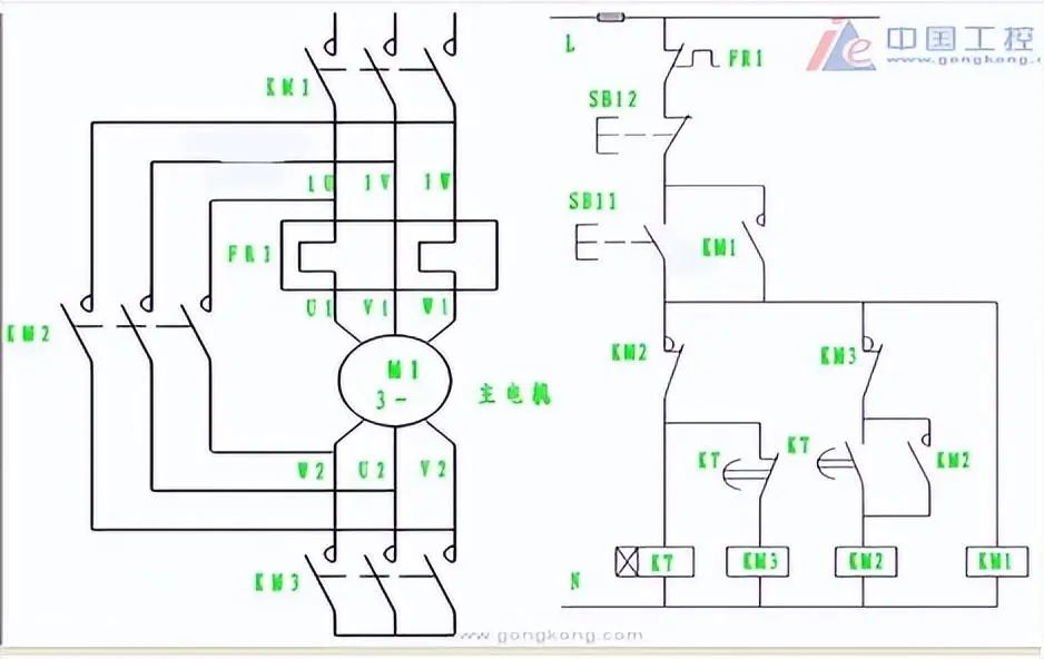
Figure 5-4: Star/Delta Start Circuit
In the figure, SB11 supplies power to contactor KM1 and star contactor KM3, and through KM1’s self-locking, the time relay K7 gets energized, and the motor runs in star connection, at this time the motor winding voltage is 220VAC. When the time relay’s delay time is up, the KT contact above KM3 opens, and the KT contact above KM2 closes, powering the delta contactor and self-locking, causing the motor to run in delta connection, at this time the winding voltage is 380VAC.
This is essentially a reduced voltage start to lessen the impact when the motor starts. It is generally recommended to use reduced voltage starting for motors greater than 7KW.
4. Delta/Double Star (Δ/YY) Speed Control Circuit
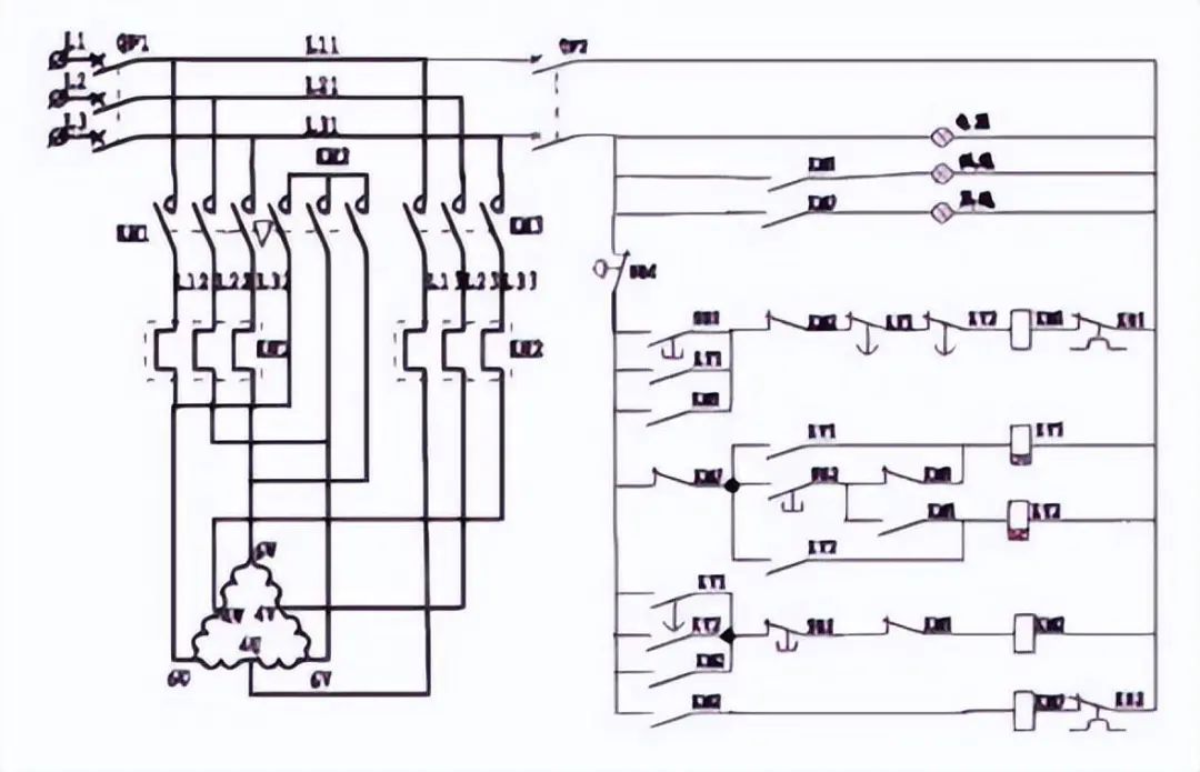
Figure 5-5: Delta/Double Star Speed Control Circuit
The delta/double star speed control circuit is essentially the pole-changing speed control of an AC asynchronous motor. The number of poles when the motor is connected in delta is half of that when connected in star.
The above circuits will not be analyzed in detail; they are assigned as homework for you to analyze their principles.
In actual exams, it is becoming increasingly uncommon to require the design of circuits using relay circuits, but the ability to design control logic using PLC ladder diagrams is essential.
4. Example of Reading Diagrams
Try to analyze the following circuit. Can you understand it?
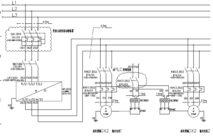
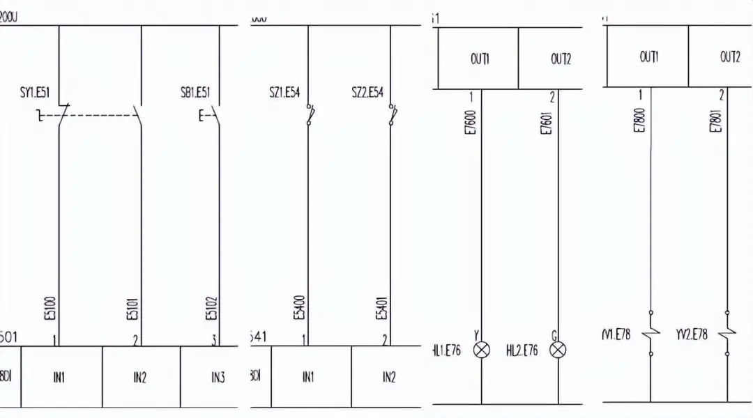
Figure 5-6: Electrical Drawing Reading Practice
The copyright of this article belongs to the original author and does not represent the views of the association. The articles pushed by the “Jiangxi Province Electronic Circuit Industry Association” are only for sharing purposes and do not represent the position of this account. If there are copyright issues, please contact us to delete.