
Whether it’s a board made by someone else or a PCB board designed and produced by yourself, the first thing to do is check the integrity of the board, such as tin plating, cracks, short circuits, open circuits, and drilling issues. If the board’s function is relatively critical, it’s also good to check the resistance value between the power supply and ground.Generally, for boards made by yourself, after tin plating is completed, components will be installed. However, if the board was made by someone else, it will just be a tin-plated PCB shell with holes, and you will need to install the components yourself when you receive it.Some people have significant information about their designed PCB boards, so they prefer to install all components at once before testing. However, it is recommended to proceed step by step.
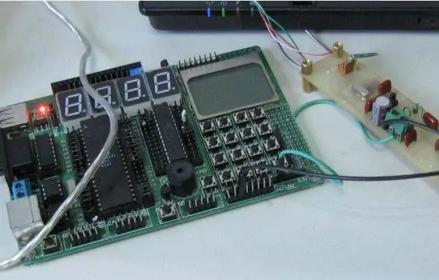
Debugging PCB Circuit BoardNew PCB board debugging can start from the power supply section. The safest method is to add a fuse and then connect the power (to be safe, it is best to use a regulated power supply).Set the overcurrent protection current on the regulated power supply, and then slowly increase the voltage of the regulated power supply. During this process, you need to monitor the board’s input current, input voltage, and output voltage.If the voltage increases without triggering the overcurrent protection and the output voltage is normal, it indicates that the power supply section of the board is fine. If it exceeds the normal output voltage or triggers overcurrent protection, then you need to troubleshoot the fault.
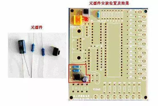
Component Installation on Circuit BoardDuring debugging, gradually install the modules. Each time you add one or several modules, follow the above steps for testing. This helps avoid some hidden errors from the initial design or incorrect component installation, which could lead to overcurrent damaging components.If a fault occurs during the installation process, you can generally troubleshoot using the following methods:Troubleshooting Method 1: Voltage Measurement Method
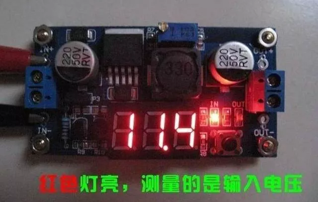
Voltage Measurement Method
When overcurrent protection occurs, do not rush to disassemble components; first, check the power pin voltage of each chip to see if it is within the normal range. Then sequentially check reference voltage, operating voltage, etc.For example: When a silicon transistor is conducting, the voltage at the BE junction will be around 0.7V, while the CE junction is generally at 0.3V or lower.If during testing the voltage at the BE junction is higher than 0.7V (excluding special transistors like Darlington), then it is likely that the BE junction is open. By checking the voltage at each point, you can exclude faults.Troubleshooting Method 2: Signal Injection Method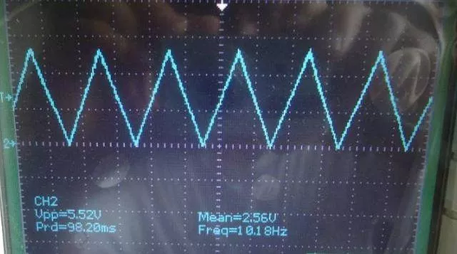 Signal Injection MethodThe signal injection method is more complicated than the voltage measurement method. When delivering the signal source to the input terminal, we need to sequentially measure the waveforms at each point afterward to find the fault point from the waveforms.Of course, you can also use tweezers to detect the input terminal. The approach is to touch the input terminal with tweezers and observe the response. This method is generally used in audio and video amplification circuits (Note: Do not use this method in hot ground circuits and high-voltage circuits, as it can lead to electric shock accidents).If this method detects that the previous stage is normal but the next stage has a response, then the fault is not in the next stage but in the previous stage.Troubleshooting Method 3: Others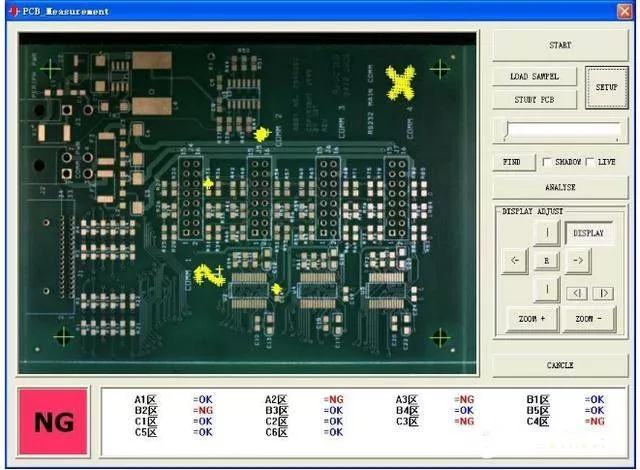
PCB Circuit Board Appearance Inspection Machine
The above two methods are relatively simple and direct. Additionally, methods such as looking, smelling, listening, and touching require some experience from engineers to detect issues.Generally, “looking” does not mean looking at the status of the testing instruments but rather checking the appearance of the components for integrity; “smelling” focuses on detecting any abnormal smells from components, such as burning or electrolyte odors. Typically, components will emit unpleasant burning smells when damaged.
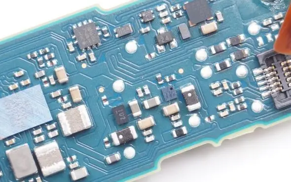
“Listening” mainly involves checking whether the sounds of the board in operation are normal; regarding “touching,” it does not mean checking if components are loose but rather feeling the temperature of the components, such as checking if a component that should be cold is hot, while one that should be hot is cold. During the touching process, do not directly squeeze with your hands to avoid burns from high temperatures.

Some Screenshots from Electronic Books

[Complete Set of Hardware Learning Materials Collection]
