Integrated circuits are made by arranging numerous components such as resistors, diodes, and transistors in the form of a circuit on semiconductor silicon wafers, then connecting pins and packaging them. Integrated circuits are commonly referred to as integrated blocks.The LM380 shown in the figure (a) is a common audio amplifier integrated circuit, with its internal circuit illustrated in figure (b).
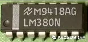
Figure (a)
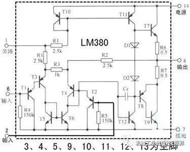
Figure (b)
For most people, it is unnecessary to understand the specific structure of the internal circuit; it suffices to know the functions of the integrated circuit and its pins.
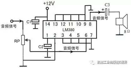
Standalone integrated circuits cannot function independently; they require corresponding peripheral components and a power supply to operate. The integrated circuit LM380 in the figure below provides power and connects to peripheral components, allowing it to amplify the audio signal input at pin 6, outputting the amplified audio signal from pin 8 to a speaker.
Sometimes, we confuse integrated circuits with chips. For example, in everyday discussions, integrated circuit design and chip design are often used interchangeably, as are the chip industry, integrated circuit industry, and IC industry. In reality, these two terms are related but distinct. Integrated circuits typically exist in the form of chips because, in a narrow sense, an integrated circuit emphasizes the circuit itself. For instance, a phase-shift oscillator formed by just five components can still be called an integrated circuit when it is presented on paper. However, when we want to apply this small integrated circuit, it must exist as a standalone physical piece or be embedded in a larger integrated circuit, relying on the chip to function. Integrated circuits focus more on circuit design and layout, while chips emphasize circuit integration, production, and packaging. In a broader sense, when discussing the industry (as distinct from others), integrated circuits can encompass various meanings related to chips.
Chips also have their unique characteristics. Broadly speaking, any semiconductor piece manufactured using microfabrication techniques can be called a chip, and it does not necessarily contain a circuit. For example, semiconductor light source chips, mechanical chips like MEMS gyroscopes, or biological chips like DNA chips. In communications and information technology, when limited to silicon integrated circuits, the intersection of chips and integrated circuits is “circuits on silicon wafers”.
This can be a concept that many people find confusing!
Characteristics of Integrated Circuits
1. Integrated circuits mainly use transistors, with fewer inductors, capacitors, and resistors, especially large capacitors, because manufacturing these components requires a large area of silicon, leading to increased costs.
2. The various circuits within integrated circuits mostly use direct connections (i.e., wires directly connect two circuits), with fewer capacitive connections, which can reduce the area of the integrated circuit and make it suitable for various frequency circuits.
3. Integrated circuits often use symmetric circuits (such as differential circuits), which can correct manufacturing process deviations.
4. Once an integrated circuit is produced, the internal circuit cannot be changed, unlike discrete component circuits, which can be modified at any time. Therefore, if a component within the integrated circuit fails, the entire integrated circuit must be replaced.
5. Integrated circuits generally cannot be used alone; they need to be combined with discrete components to form practical circuits. For integrated circuits, most electronic technicians only need to know the functional circuit within, which means understanding the internal structure block diagram and the functions of each pin.
Types of Integrated Circuits
There are many types of integrated circuits, and there are various classification methods. Here are a few major classification methods:
1. By the functions represented by the integrated circuit, they can be classified into analog integrated circuits, digital integrated circuits, interface circuits, and special circuits.
2. By the type of active devices, integrated circuits can be divided into bipolar, unipolar, and bipolar-unipolar hybrid types. Bipolar integrated circuits mainly use diodes and transistors internally. Unipolar integrated circuits mainly use MOS field-effect transistors. Bipolar-unipolar hybrid integrated circuits are made using both MOS and bipolar compatible processes, thus incorporating the advantages of both.
3. By the integration level of integrated circuits, they can be classified into small-scale integrated circuits (SSI), medium-scale integrated circuits (MSI), large-scale integrated circuits (LSI), and very-large-scale integrated circuits (VLSI).
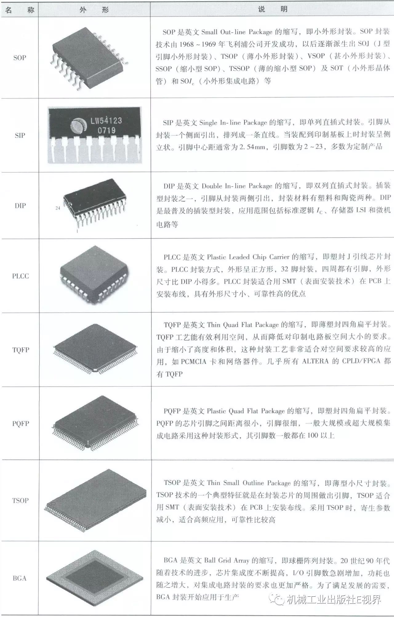
Packaging Forms
Packaging refers to connecting the circuit pins on the silicon wafer to external pins via wires for connection with other devices. The packaging form refers to the casing used for mounting semiconductor integrated circuit chips.
Pin Identification
Integrated circuits have many pins, ranging from a few to hundreds, with different functions for each pin. Therefore, it is essential to match the pins correctly when using them; otherwise, the integrated circuit may not work or could be damaged. Thus, it is crucial to know the pin identification methods for integrated circuits.
Regardless of the integrated circuit, they all have a marking indicating the first pin. Common markings include small dots, small bumps, notches, or corners. After identifying this pin, the following pins are numbered counterclockwise as 2, 3, 4…, as shown in figure (a). For single-row or dual-row pin integrated circuits, if the surface has markings, when identifying pins, align with the marked text; the lower left corner of the text indicates pin 1, and then number counterclockwise as 2, 3, 4…, as shown in figure (b).
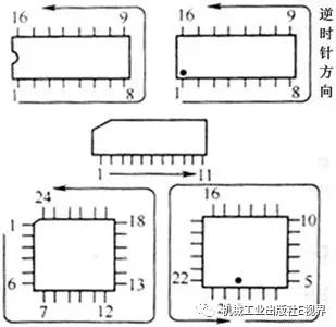
Figure (a)
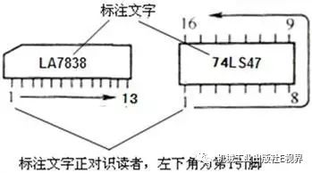
Figure (b)
Good and Bad Testing
Below are some commonly used methods for testing the good and bad status of integrated circuits:
1.Open Circuit Resistance Measurement Method
The open circuit resistance measurement method refers to the method of determining good or bad status by measuring the resistance between each pin of the integrated circuit and the ground pin when the integrated circuit is not connected to other circuits.
All integrated circuits have a ground pin (GND), and there is a certain resistance between each pin and the ground pin. Since the internal circuits of integrated circuits of the same model are identical, the resistances between the pins and the ground pin of normal integrated circuits of the same model are also the same.Based on this, the open circuit resistance measurement method can be used to determine the status of the integrated circuit.
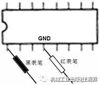
During testing, set the multimeter to the R×100Ω range, fix the red probe to the ground pin of the integrated circuit being tested, and connect the black probe to each of the other pins sequentially, as shown in the figure. Measure and record the resistance between each pin and the ground pin, then use the same method to measure the resistances of the pins of a normal integrated circuit of the same model, and compare the two sets of resistance measurements. If both sets are identical, the tested integrated circuit is normal; if there is a significant difference in resistance for any pin, the tested integrated circuit is damaged. It is best to measure the resistance of each pin using the same range; if a pin’s resistance is too large or too small to observe and a range change is necessary, the same range must be used when measuring the corresponding pin of the normal integrated circuit. This is because most of the internal components of integrated circuits are semiconductor devices, and different ohm ranges provide different currents. When measuring the same pin with different ohm ranges, the degree of conduction of the internal components may vary, leading to discrepancies in the resistance values obtained.
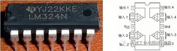
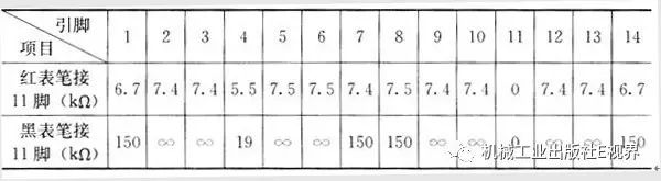
Using the open circuit resistance measurement method to determine the good or bad status of integrated circuits is relatively straightforward and applicable to most integrated circuits. Its drawback is that it requires a normal integrated circuit of the same model for comparison. To resolve this issue, it is advisable to regularly measure the open circuit resistance data of commonly used integrated circuits for future reference. Additionally, relevant data can be found in some literature. The following figure shows a commonly used integrated circuit, the LM324, which has four operational amplifiers internally. The table below lists its open circuit resistance data, measured using a digital multimeter set to the 200kΩ range. The table contains two sets of data: one where the red probe connects to pin 11 (the ground pin) and the black probe connects to the other pins, and another where the black probe connects to pin 11 and the red probe connects to the other pins. When testing the LM324, the digital multimeter should also be set to the 200kΩ range, and the measured data should be compared with the data in the table to determine the status of the tested integrated circuit.
2.In-Circuit Testing Method
The in-circuit testing method refers to the method of testing the integrated circuit while it is connected to other circuits.
1. In-Circuit DC Voltage Measurement Method
The in-circuit DC voltage measurement method involves measuring the voltage at each pin relative to ground while the circuit is powered on and comparing it with reference voltages to identify faults.
Key points for using the in-circuit DC voltage measurement method are as follows:
1. To minimize the effect of the multimeter’s internal resistance during measurement, use a multimeter with high internal resistance whenever possible. For example, the MF47 multimeter’s DC voltage range has an internal resistance of 20kΩ/V, so when measuring on the 10V range, the internal resistance is 200kΩ. During measurement, the multimeter’s internal resistance will cause some current division, resulting in a slightly lower measured voltage than the actual voltage. The higher the internal resistance, the smaller the effect on the measured circuit voltage. The MF50 multimeter has a smaller internal resistance of 10kΩ/V, which means it will have a greater impact on the circuit voltage than the MF47 multimeter.
2. During testing, first measure whether the power supply pin voltage is normal. If the power supply pin voltage is not normal, check the power supply circuit. If the power supply circuit is normal, the integrated circuit may be damaged internally, or some peripheral components of the integrated circuit may be damaged, causing the power supply pin voltage to be abnormal.
3. After confirming that the power supply pin voltage of the integrated circuit is normal, further measure whether the voltages at the other pins are normal. If individual pin voltages are abnormal, first check the peripheral components of that pin. If the peripheral components are normal, the integrated circuit is likely damaged. If multiple pin voltages are abnormal, analyze whether these pin voltage changes are caused by changes in the voltage of one or more other pins based on the internal structure of the integrated circuit and the working principles of the peripheral circuits. Focus on checking the peripheral components of these pins; if they are normal, the integrated circuit is likely damaged.
4. Some integrated circuits may have different pin voltages under signal input (dynamic) and no signal input (static) conditions. When comparing the measured voltages with the reference voltages of the integrated circuit, take note of the measurement conditions. The measured voltages should be obtained under the same conditions. For example, the reference voltages marked on the schematic of a color television are usually measured while receiving a color bar signal, so the television should be set to receive a color bar signal during measurement as well.
5. Some electronic products have various operating modes, and the voltages at certain pins of the integrated circuit may change during different operating modes and transitions between modes. For such integrated circuits, understanding the circuit’s working principles is essential for accurate measurement and judgment. For example, in a DVD player, the voltages at certain pins of the integrated circuit may change during disc insertion, disc ejection, disc searching, and reading.
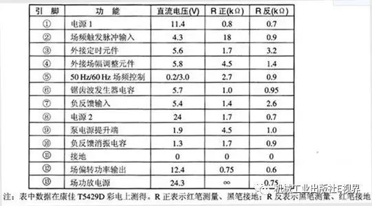
The reference values for the DC voltages at the pins of the integrated circuit can be found in relevant schematics or literature. The table below lists the functions, DC voltages, and in-circuit resistance reference values for the commonly used field scanning output integrated circuit LA7837.
2. In-Circuit Resistance Measurement Method
The in-circuit resistance measurement method involves measuring the forward and reverse resistance values of the integrated circuit’s pins and peripheral components with the power supply turned off, and comparing them with reference data to determine faults.
Key points for using the in-circuit resistance measurement method are as follows:
1. Before measuring, ensure that the tested circuit’s power supply is turned off to avoid damaging components and instruments, and to ensure accurate resistance values.
2. The multimeter’s R×10kΩ range uses a 9V battery internally. Some integrated circuits operate at lower voltages, such as 3.3V or 5V. To prevent high voltage from damaging the tested integrated circuit, it is best to select the R×100Ω or R×1kΩ range for measurement.
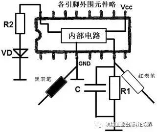
3. When measuring the resistance of each pin of the integrated circuit, one probe should be connected to ground, and the other probe should be connected to the integrated circuit’s pins, as shown in the figure. The measured resistance value represents the parallel resistance of the pin’s peripheral components (R1, C) and the integrated circuit’s internal circuit and related peripheral components. If a significant difference is found between the measured resistance of a particular pin and the reference resistance, first check the peripheral components of that pin. If the peripheral components are normal, it is usually an indication of internal damage to the integrated circuit. If multiple pin resistances are abnormal, it is highly likely that the integrated circuit is damaged, but it cannot completely rule out the possibility of damage to the peripheral components of these pins.
The reference resistance values for the pins of the integrated circuit can be found in relevant schematics or literature.
3. In-Circuit Total Current Measurement Method
The in-circuit total current measurement method involves measuring the total current of the integrated circuit to determine faults.
Most internal components of integrated circuits are connected directly to form circuits. When a component fails or becomes open circuit, it usually affects the subsequent circuitry, causing the total operating current of the entire integrated circuit to decrease or increase. After measuring the total current of the integrated circuit, compare it with the reference current; both excessively high or low currents indicate a fault in the integrated circuit or peripheral components. Schematic diagrams and relevant literature typically do not provide reference data for the total current of integrated circuits; this data can be obtained through actual measurements in normal electronic products.
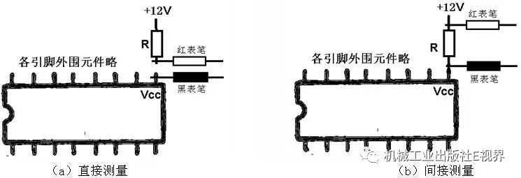
To measure the total current of the integrated circuit, as shown in the figure, you can either disconnect the power pin of the integrated circuit for direct current measurement or measure the voltage across the power supply resistance and use I=U/R to calculate the current value.
4. Elimination and Substitution Methods
Whether using the open circuit resistance measurement method or the in-circuit testing method, it is essential to have corresponding reference data. If reference data cannot be obtained, elimination and substitution methods can be employed.
1. Elimination Method
When using integrated circuits, some external components must be connected. If the integrated circuit does not work, it may be due to damage to the integrated circuit itself or to the peripheral components. The elimination method involves first checking the peripheral components of each pin of the integrated circuit. If all peripheral components are normal, then the cause of the integrated circuit’s malfunction can be ruled out as due to peripheral component damage, indicating that the fault lies within the integrated circuit itself.
Key points for using the elimination method are as follows:
1. During testing, it is best to use the elimination method after confirming that the power supply of the integrated circuit is normal. If the power supply pin voltage is abnormal, first check and repair the power supply circuit.
2. Some integrated circuits can work normally with just themselves and their peripheral components, while others (especially digital integrated circuits) require other circuits to provide relevant control signals (or feedback signals) to function correctly. For such integrated circuits, in addition to checking whether the peripheral components are normal, it is also necessary to verify that the integrated circuit is receiving the relevant control signals.
3. The elimination method is quicker for integrated circuits with fewer peripheral components. For integrated circuits with many peripheral components, it is usually more efficient to first check the peripheral components of some important pins and components that are prone to failure.
2. Substitution Method
The substitution method involves directly replacing the suspected damaged integrated circuit with a normal one of the same model. If the fault disappears, the original integrated circuit is damaged. If the fault persists, it may be due to damage to the peripheral components of the integrated circuit, a faulty replacement integrated circuit, or the replacement integrated circuit being damaged due to unresolved issues with the peripheral components. Additionally, some integrated circuits may not function properly if they do not receive control signals from other circuits.
Key points for using the substitution method are as follows:
1. Since directly replacing the integrated circuit without ruling out peripheral component faults may cause the new integrated circuit to be damaged, it is advisable to replace integrated circuits that operate at high voltages and currents only after ensuring that the peripheral components are normal. For integrated circuits operating at low voltages, it is also advisable to replace them only after confirming that some key peripheral components are functioning correctly.
2. Some digital integrated circuits contain programs. If the program is corrupted, the integrated circuit may not function correctly, even if the peripheral components and control signals are normal. In such cases, you can use specific devices to reprogram the integrated circuit or replace it with a pre-programmed one.
Disassembly of Through-Hole Integrated Circuits
When repairing circuits, it is often necessary to remove integrated circuits from printed circuit boards. Due to the numerous pins of integrated circuits, disassembly can be challenging, and improper disassembly may damage the integrated circuit and the circuit board. Below are several commonly used methods for disassembling integrated circuits.
1. Using a Syringe Needle for Disassembly
When disassembling integrated circuits, you can use a stainless steel hollow tube or a syringe needle (available in electronics markets) as shown in figure (a). The disassembly method is illustrated in figure (b). Touch the solder point of a pin on the integrated circuit with the soldering iron tip. When the solder at that pin melts, place a suitably sized syringe needle over that pin and rotate it to detach the integrated circuit’s pin from the printed circuit board’s solder copper foil. Then, remove the soldering iron tip and carefully pull out the syringe needle. This process can be repeated for each pin until all pins are detached from the printed circuit board.
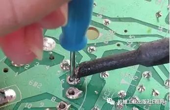
Figure (a)
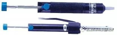
Figure (b)
2. Using a Desoldering Pump for Disassembly
A desoldering pump is a repair tool that generates suction either manually or electrically to remove solder from the circuit board’s copper foil. The desoldering pump is shown in the figure below, with the lower part featuring heating functionality, also known as a desoldering soldering iron.
The operation for disassembling integrated circuits using a desoldering pump is illustrated in the figure below. The detailed process is as follows:
1. Press down on the desoldering pump’s piston to lock it in place.
2. Use the soldering iron to heat the solder point until the solder melts.
3. Remove the soldering iron and quickly place the desoldering pump’s nozzle over the solder point, pressing the button to allow the piston to spring up, creating suction that pulls the solder into the desoldering pump.
4. If the solder is not completely removed in one go, the operation can be repeated multiple times.
Once all the solder from the pins has been removed, the integrated circuit can then be taken off the circuit board.
3. Using a Brush with a Soldering Iron for Disassembly
This disassembly method is relatively simple, requiring only a soldering iron and a small brush. When using this method to disassemble an integrated circuit, first heat the solder at the pins of the integrated circuit with the soldering iron. Once the solder has melted, immediately use the brush to sweep away the melted solder. Repeat this process for the other pins. Once all the solder has been cleared from the pins, gently pry the integrated circuit off using tweezers or a small flathead screwdriver.
4. Using Multi-Stranded Copper Wire for Desoldering
When using this method for disassembly, multi-stranded copper wire is required, as shown in the figure below.
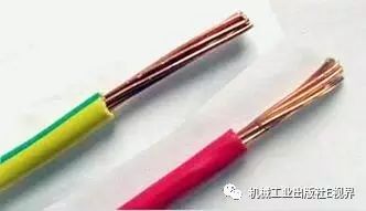
The operation for disassembling integrated circuits using multi-stranded copper wire is as follows:
1. Remove the plastic insulation from the multi-stranded copper wire, and place the wire in rosin to heat it with a soldering iron, allowing it to absorb the rosin.
2. Place the multi-stranded copper wire on the pin of the integrated circuit and heat it with a soldering iron. The solder on the pin will be absorbed by the rosin-coated copper wire. Cut off the portion of the wire that has absorbed the solder. Repeat the operation several times until all the solder on the integrated circuit pins has been removed. Then, gently pry off the integrated circuit using tweezers or a small flathead screwdriver.
5. Increasing Solder Melting for Disassembly
This disassembly method does not require additional tools or materials, making it particularly suitable for disassembling single-row or dual-row integrated circuits with a limited number of pins.
The operation process for disassembling integrated circuits by increasing solder melting is as follows:
When disassembling, first add some solder to one row of the integrated circuit pins to connect all the solder points in that row. Then, heat the middle pin of that row with a soldering iron and move towards the ends. This will utilize the thermal conduction of the solder to melt the solder on all pins in that row. Gently pry the integrated circuit upwards at that row using tweezers or a small flathead screwdriver. Repeat the heating and prying process for the other row of pins until the integrated circuit is removed. Generally, heating each row twice is sufficient for disassembly.
6. Using a Hot Air Rework Station or Hot Air Gun for Disassembly
A hot air rework station or hot air gun is shown in the figure below, with a nozzle capable of blowing hot air at temperatures reaching several hundred degrees Celsius. This hot air can melt the solder on the pins of the integrated circuit, allowing for its removal.
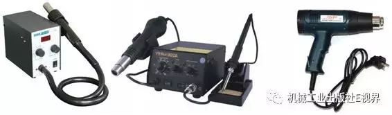
During disassembly, be careful when using a single nozzle; keep the nozzle vertical to the integrated circuit being removed and move it around the pins to evenly heat the solder. Avoid letting the nozzle touch the integrated circuit or surrounding peripheral components, and ensure accurate positioning of the hot air.
Disassembly and Welding of Surface-Mount Integrated Circuits
1. Disassembly
Surface-mount integrated circuits have many pins arranged closely, with some having pins on all four sides. If the disassembly method is improper, it may be difficult to remove the circuit, and worse, it may damage the integrated circuit pins and the copper foil on the circuit board. The disassembly of surface-mount integrated circuits typically involves using a hot air rework station or hot air gun.
The disassembly process for surface-mount integrated circuits is as follows:
1. Before disassembly, carefully observe the position and orientation of the integrated circuit on the circuit board and make a mark to ensure that it is installed correctly according to the corresponding mark during soldering, avoiding installation errors.
2. Use a small brush to clean any debris around the surface-mount integrated circuit, and apply a small amount of rosin powder or rosin liquid to the pins.
3. Adjust the temperature and airflow of the hot air gun. The temperature switch is usually set to levels 3 to 5, while the airflow switch is set to levels 2 to 3.
4. When using a single nozzle for disassembly, ensure that the nozzle remains vertical to the integrated circuit being removed and move it around the pins to evenly heat them. The nozzle should not touch the integrated circuit or surrounding components, and the position of the hot air should be precise, avoiding blowing onto surrounding components.
5. Once all the solder on the integrated circuit pins has melted, use tweezers to lift or remove the integrated circuit. Do not apply excessive force, as this may easily damage the copper foil connected to the integrated circuit.
For repair personnel without a hot air rework station or hot air gun, the following method can be used to disassemble surface-mount integrated circuits:
First, apply rosin to one row of the integrated circuit pins and connect all the solder points in that row with solder. Then, heat the solder with a soldering iron. Once the solder on that row melts, use a thin blade (such as a razor blade) to push between the circuit board and the pins, remove the soldering iron, and wait a few seconds before pulling out the blade. This will detach that row of pins from the circuit board. Repeat this method for the other pins until the entire integrated circuit is removed.
2. Welding
The welding process for surface-mount integrated circuits is as follows:
1. Use a soldering iron to smooth out the solder points on the circuit board. If necessary, add solder to any points that have insufficient solder, then clean the area around the solder points with alcohol.
2. Align the surface-mount integrated circuit with the soldering position on the circuit board, and solder the four diagonal pins with a soldering iron to secure the integrated circuit. Apply a small amount of rosin liquid or sprinkle some rosin powder on the pins.
3. If using a hot air gun for soldering, blow hot air around the pins of the integrated circuit until the solder on the circuit board melts, then remove the hot air gun, and the pins will adhere to the solder points on the circuit board. If using a soldering iron for soldering, dip a small amount of solder on the soldering iron tip and drag it along one row of pins to solder them to the circuit board. If some pins of the integrated circuit are shorted due to excess solder, use multi-stranded copper wire to remove the excess solder, and then apply rosin liquid to the area and heat it with a soldering iron to automatically disconnect any remaining solder between the pins.
4. After soldering, check for any short circuits or cold solder joints between the integrated circuit pins. Use a magnifying glass or multimeter for inspection. If there are any cold solder joints, use a pointed soldering iron to re-solder them, and finally clean the rosin around the integrated circuit with anhydrous alcohol.
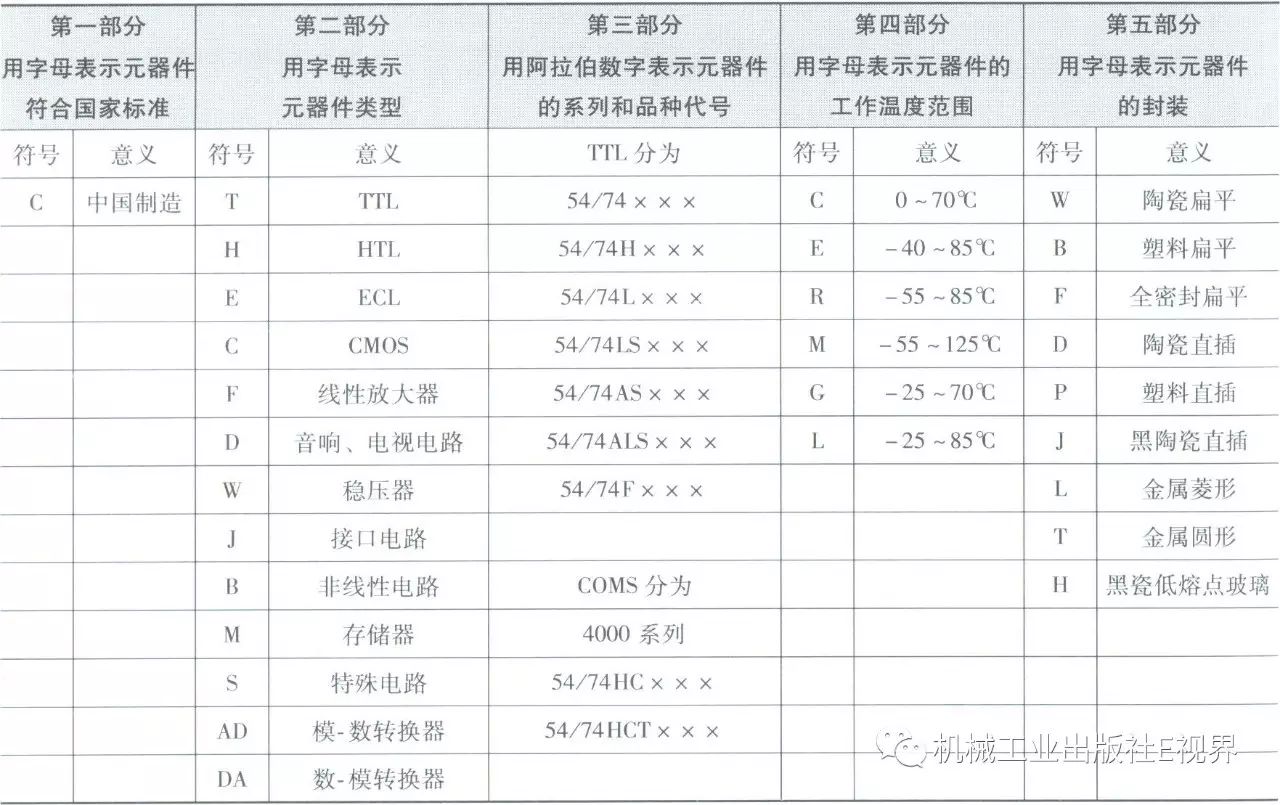
Naming Methods for Integrated Circuit Models
Source: “Learning Electronic Components Made Super Simple (Completely Upgraded Edition)”
Click the image to view book details and purchase
This book provides a comprehensive introduction to commonly used electronic components, progressing from basic to advanced, and offers free online tutoring.
We also have many other books available on electronic component knowledge! Please click the “Read the Original” link at the bottom of the article to view!
Highlights from January:
Book List | How to Become an Excellent Electrician or Electrical Engineer? Practical Edition!
Electrical Wiring Standards, One Article is Enough!
To Master PLC, You Must Learn This! The Most Common PLC Graphic Programming Language in IEC61131 Standard!
Why Can a Capacitor (DC) Charge from a Battery (DC)?
Is It Necessary for Electricians to Assemble Distribution Boxes to Be Considered Beginners? WORD Brother, First Tell Me the Difference Between Distribution Boxes and Distribution Cabinets!
How to Learn PLC? See How Old Pa Says It! Full of Practical Content, No Fluff, Guaranteed to Be Read in One Go!
Absolutely Worth Collecting! Common Fault Diagnosis and Handling Techniques for Single-Phase Induction Motors!
Let’s Chat with Old Pa! As an Electrical Engineer, Where Does Your Greatest Sense of Achievement Come From?
What Are the Differences Between Electricians in China and Japan When Wiring Indoors?
Four Classic Application Examples of Basic PLC Instructions
The Most Accurate Explanation of the Role of Zero Ohm Resistors!
Electrical Circuit Basics: Delta-Y and Y-Delta Transformations, Are They Difficult?
Foreign Wiring Tools, A Blessing for Electricians! It Makes Things So Much Easier!
Homemade Household Generator, No Fuel Needed, Enough Power for the Whole Family! Is It a Scam? Or Are There Experts in the Community?
Is There Anything That Must Not Be Missing in PLC Application Program Design?
Interesting Article! Easily Teach You to Master Hardware Circuit Design!
How is Three-Phase Electricity Generated? Understand in Two Minutes!
The First Article of the New Year, Don’t Miss It, The Most Comprehensive PLC Programming Algorithm!
You can view all technical articles from 2016 and 2015 by clicking the “WeChat Directory” menu below the public account, selecting “Article Collection”, or you can search for technical articles by keywords using the “WeChat Directory” menu and selecting “Search Within the Account”.

The Mechanical Industry Press E-World WeChat Group has been established
Please click the “More Interactions” – “WeChat Group” menu below the public account to join!