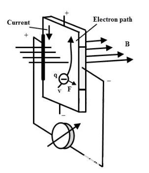
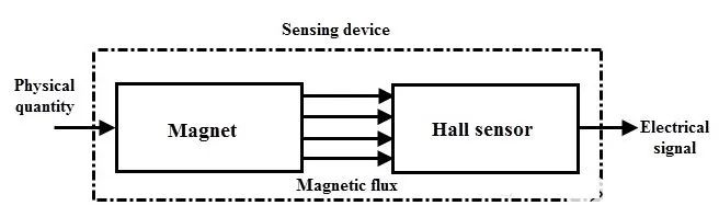
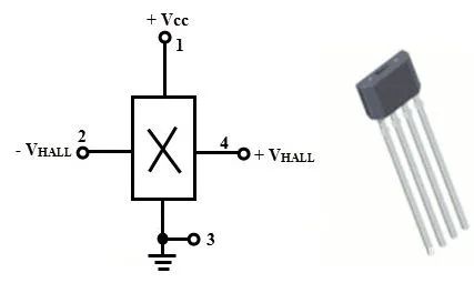
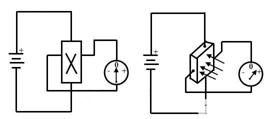
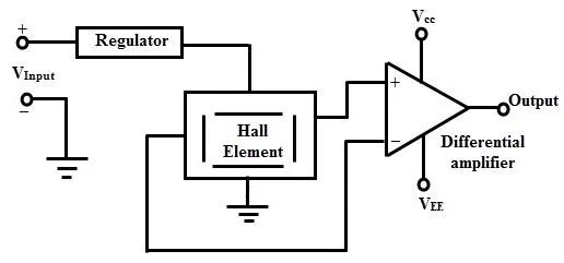
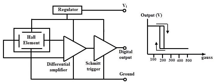
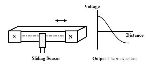
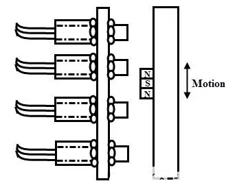
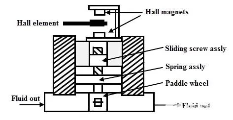
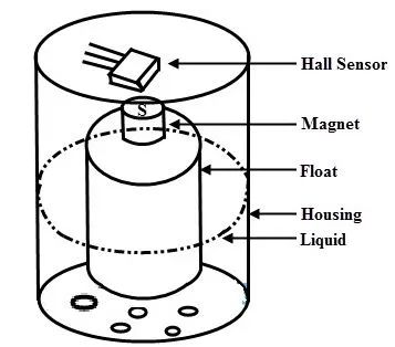
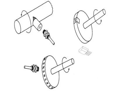
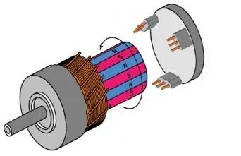
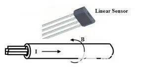
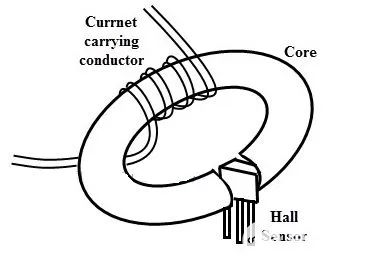
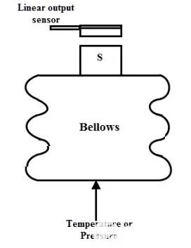
Among various sensing technologies, the most commonly used and widespread method for detecting magnetic fields is the Hall effect method. Based on the Hall effect, many Hall effect sensors or transducers have been found in various applications, primarily used for sensing proximity, speed, current, and position.This is due to the ability to construct Hall effect sensors on integrated circuits, using auxiliary signal processing circuits on the same silicon chip. Due to advantages such as small size, ruggedness, ease of use, and cost integration, Hall effect sensors are the preferred choice for many magnetic measurement applications.Some application areas for these Hall effect sensors include their use as encoders, speed sensors, and stroke end sensors in industrial control; as disk drive index sensors and commutation for brushless fans in computers; as anti-lock braking system (ABS) and ignition timing in automobiles; and as exercise equipment in consumer devices.About Hall Effect TheoryThe Hall effect was discovered experimentally by Edwin Hall in 1879 at Johns Hopkins University. Due to the instruments available at the time, and the subtle nature of the experiment, the voltage obtained from the material was very low (in microvolts). Therefore, it was impossible to use the Hall effect outside the laboratory until suitable materials were developed. The development of semiconductor materials created high-quality transducers for practical applications of the Hall effect.The Hall effect refers to the generation of voltage at the relative edges of a current-carrying conductor placed in a magnetic field. When current flows through a conductor placed in a magnetic field, a potential difference is created in a direction perpendicular to both the magnetic field and the current, which is proportional to the current and the magnetic field. This phenomenon is called the Hall effect, which forms the basis for many magnetic field measurement instruments and devices.Consider a simple setup to illustrate the Hall effect as shown below. The conductive material or plate is powered by a battery, with current (I) flowing through it. A pair of probes from a voltmeter is connected to the sides of the plate, ensuring that the voltage measured in the absence of a magnetic field is zero.When a magnetic field is applied to the plate at a right angle to the current, a small voltage will appear due to the current distribution in the conductor. This force acts on the current and gathers the current to one side of the wire or conductor, creating a potential difference across the conductor. If the polarity of the magnetic field is reversed, the induced voltage will also reverse across the plate. This phenomenon is known as the Hall effect.The Hall effect is based on the interaction between an external magnetic field and moving charge carriers, with the lateral force acting on moving electrons given by: F=qvB.Where B is the magnetic flux density, v is the speed of the electrons, and q is the charge of the electrons. In the above diagram, it is precisely due to the magnetic field that the motion of the charges is deflected. A flat conductive strip is placed in the magnetic field, with additional contacts on both sides of the conductive strip connected to a voltmeter.The lower and upper ends of the conductive strip are connected to a power source, and due to the presence of magnetic flux, the moving electrons are deflected towards the right side of the strip due to the deflection force. This results in the right side being more negatively charged than the left side, creating a potential difference.This voltage is called the Hall voltage, and its magnitude and direction depend on the size and direction of the current and the magnetic field. The calculation formula for the Hall voltage is:VH=HIB sinαWhere H is the overall sensitivity coefficient, which depends on the plate material, temperature, and its geometry; α is the angle between the magnetic field vector and the Hall plate; and I is the current density.Additionally, the overall sensitivity depends on the Hall coefficient, which is the transverse potential gradient per unit current density per unit magnetic field strength. Thus, the Hall coefficient is given by:H = 1/Ncq,Where c is the speed of light, and N is the number of electrons per unit volume.Hall Effect SensorsIf a sensor uses the Hall effect to sense the presence of a magnetic field, it is referred to as a Hall effect sensor. The basic element of a magnetic sensor is the Hall element, which is typically packaged in a four-terminal housing, where two terminals are control terminals, and the other two are differential output terminals.The control current is applied to the control terminals, while the output is observed at the differential output terminals. A basic Hall effect sensor converts the magnetic field into an electrical signal. The magnetic system converts physical quantities such as position, speed, current, and temperature into a magnetic field, which can then be sensed by the Hall effect sensor.Hall effect sensors are made from silicon materials and are mainly divided into two types: basic sensors and integrated sensors. The Hall coefficient and current density of the active element are two important parameters to consider when manufacturing Hall effect sensors to produce high output voltage.Therefore, high Hall coefficient and low resistance are two important requirements for Hall elements. Some materials used to manufacture these sensor elements include InSb, Ge, InAs, and GaAs.Hall Effect Integrated Circuit (IC) SensorsThis integrated technology, combined with the principles of the Hall effect, produces Hall effect IC switches. Compared to photoelectric or inductive sensors, Hall effect IC switches are more efficient, cost-effective, and higher in efficiency.This sensor is a single integrated circuit chip with various components built-in, such as signal amplifiers, Hall voltage generators, and Schmitt trigger circuits. These ICs can detect changes in magnetic field strength in ferromagnetic materials, permanent magnets, or electromagnets under applied bias.These ICs are used in various applications such as alignment control, speed control, ignition systems, mechanical limit switches, machine tools, computers, keyboards, buttons, and security systems.Hall effect ICs are manufactured using various configurations of silicon CMOS technology. The above figure shows the Hall effect sensor IC in a 4-pin package. Of the total 4 pins, 2 are connected to a constant voltage source, while the other two are connected to a voltmeter.The connection layout is shown in the diagram below. When there is no magnetic field, the measured thin plate voltage can be negligible. When the magnetic field is applied to the biased Hall effect sensor in a manner where the magnetic flux lines are perpendicular to the current flowing through the Hall element, the output of the Hall IC generates a voltage proportional to the magnetic field strength.Main TypesHall effect sensors require a signal conditioning circuit to make their output usable for many other applications. This signal conditioning circuit performs amplification, voltage regulation, temperature compensation, and linearization. Currently, there are two main types of Hall effect sensors: analog Hall effect sensors and bipolar Hall effect sensors.1. Analog Hall Effect SensorsCompared to basic Hall sensors, analog Hall effect sensors operate over a wider voltage range and are stable even in noisy environments. The diagram below shows an analog output Hall effect device, which generates an analog voltage proportional to the magnetic field it is exposed to.The amplifier has a bias or fixed offset, so when the magnetic field is absent, the bias voltage appears at the output, which is considered zero voltage. The magnetic field at the Hall element can be either positive or negative. Therefore, when a positive magnetic field is sensed, the output voltage increases above the zero value, while when a negative magnetic field is sensed, the output decreases below the zero value.Using these sensors, the output voltage is within the limits imposed by the power supply, so before reaching the power supply limit, the amplifier will begin to saturate, as shown in the above diagram. It is important to note that saturation occurs in the amplifier and does not occur in the Hall element, so larger magnetic fields do not damage the Hall effect sensor.Moreover, these sensors are not very linear concerning the magnetic field; therefore, they require appropriate calibration for high-precision measurements. Meanwhile, the addition of push-pull transistors, open-collector or open-emitter at the output of the differential amplifier increases the interface flexibility of the device.2. Bipolar Hall Effect SensorsThese sensors have two polarities for output: on or off, and these sensors are also known as digital output Hall effect sensors. Additionally, the amplifier includes a built-in Schmitt trigger with threshold levels. This Schmitt trigger device converts the analog signal to a digital output by comparing the differential amplifier output with a fixed reference.Thus, when the differential amplifier output exceeds the reference or preset value, the Schmitt trigger turns on, while it turns off when below the reference value.The two-level output signal as a function of the magnetic field is shown in the diagram below. In this case, hysteresis eliminates unwanted oscillations by introducing a dead zone, where the action is disabled after the reference or preset value is passed.Main ApplicationsDepending on the application, Hall effect sensors come in various configurations. These are very popular measuring devices used in industrial process control, biomedical, automotive, telecommunications, ATMs, and various other application fields.Hall effect sensors are widely used asposition sensors, level measurement, limit switches, and flow measurement. Some devices operate based on the Hall effect, such as Hall effect current sensors, Hall effect blade switches, and Hall effect magnetic field strength sensors. Some of these applications are described below.1. Position SensorsHall effect sensors are used to sense sliding motion, where there will be a strictly controlled gap between the Hall element and the magnet, as shown in the diagram below:When the magnet moves back and forth within the fixed gap, the induced magnetic field will change. When the element approaches the north pole, the field will be negative, and when it approaches the south pole, the magnetic field will be positive.These sensors are also known as proximity sensors used for precise positioning. The diagram below shows four digital output bipolar sensors, which are screwed into an aluminum housing and driven by a magnet mounted on a rod.When the magnet moves within an acceptable size range, these sensors generate signals. Starting from the reference surface, these signals represent the measured distance. This type of arrangement is also known as multi-position sensing, with the best examples of such applications being the detection of various lens positions in photo processing equipment.2. Flow MeasurementThe diagram below shows a Hall effect sensor used for flow measurement. The chamber has openings for fluid to flow in and out, and the fluid flows through these openings. A spring-loaded paddle with a threaded shaft causes the magnetic component to move back and forth towards the Hall magnet.As the flow rate through the chamber increases, the spring-loaded paddle rotates the threaded shaft. Therefore, when the shaft rotates, the magnetic component rises, causing the sensor to be energized. When the flow decreases, the spring coil causes the magnetic component to drop. Thus, the transducer output decreases. The entire arrangement is calibrated to maintain a linear relationship between the measured voltage and flow rate.3. Level MeasurementIn this method, Hall effect sensors are used to determine the height of a float, thereby measuring the liquid level in a tank. The diagram below illustrates the arrangement of the float and Hall effect element in the tank. The float is attached to a magnet, so its movement drives the change in the magnetic field distance from the Hall element.As the liquid level rises, the magnet moves closer to the sensor, causing the output voltage to increase, while when the liquid level drops, the voltage decreases. Thus, this system provides simple liquid level measurement without requiring any electrical connections inside the tank.4. Speed SensorsSpeed or RPM sensing is the most common application of Hall effect sensors. In speed sensing, Hall effect sensors are fixed in a manner facing a rotating magnet. This rotating magnet generates the magnetic field required to operate the sensor or Hall element.The arrangement of the rotating magnet can vary depending on the convenience of the application. Some of these arrangements involve mounting a single magnet on a shaft or hub or using a ring magnet. The Hall sensor emits output pulses every time it faces the magnet.Furthermore, these pulses are controlled by a processor to determine and display the speed in RPM. These sensors can be either digital or linear analog output sensors.5. Brushless DC Motor SensorsThe power distribution of brushless DC motors is controlled by electronic commutation rather than mechanical commutation. Three bipolar Hall effect sensors are positioned near the rotor magnetic pole surface at one end of the stator to perform electronic commutation. To operate these sensors, permanent magnetic materials are installed on the rotor shaft. These sensors measure the position of the rotating magnet to determine when current should be applied to the motor coil, allowing the magnet to rotate in the correct direction.The information sensed by the Hall effect sensors feeds into the logic circuit, which further encodes the information and controls the drive circuit. This type of feedback mechanism provided by Hall effect sensors is used to measure the speed and position of the rotor for many BLDC motor control applications, as it offers greater flexibility.6. Current SensorsHall effect current sensors are used to measure AC and DC currents. By using linear analog Hall effect sensors, currents ranging from 250mA to several thousand amperes can be measured.This isolated analog output voltage is further digitized, and level shifting and temperature compensation are achieved by adding amplifiers. The current-carrying conductor is always surrounded by a magnetic field, so a linear Hall effect sensor is placed near this magnetic field, generating a voltage at the output of the sensor, as shown in the diagram below. This voltage is proportional to the strength of the magnetic field around the conductor.By combining Hall effect sensors with electromagnets, a more sensitive and efficient isolated current sensing device can be achieved. This arrangement consists of a slotted ferrite toroidal core and a Hall effect IC sensor located in the gap.The sensor is surrounded by the magnetic core, which acts as a flux concentrator, focusing the induced magnetic field onto the position where the Hall element is placed, as shown in the diagram below.By varying the number of windings on the core, the sensor can measure currents from a few amperes to several thousand amperes. The output voltage of the Hall effect sensor is proportional to the current flowing through the windings, thus proportional to the current measurement.7. Temperature or Pressure SensorsHall effect sensors can also be used as pressure and temperature sensors, which are combined with pressure deflection diaphragms that have appropriate magnets, with the magnetic components of the bellows actuating the Hall effect element back and forth.In the case of pressure measurement, the bellows expand and contract. The changes in the bellows lead to the magnetic component moving closer to the Hall effect element. Thus, the generated output voltage is proportional to the applied pressure.In the case of temperature measurement, the bellows component is sealed with gas that has known thermal expansion characteristics. When the chamber is heated, the gas inside the bellows expands, causing the sensor to generate a voltage proportional to the temperature.ConclusionFrom the above introduction, it is not difficult to see that Hall effect sensors are a type of magnetic field sensor made based on the Hall effect, and they can be widely applied in industrial automation technology, detection technology, and information processing. The Hall effect is a fundamental method for studying the properties of semiconductor materials.Additionally, Hall effect sensors are also transducers that convert changes in the magnetic field into changes in output voltage. Hall sensors are primarily used for measuring magnetic fields, but they can also measure physical quantities that generate and affect magnetic fields, such as those used in proximity switches, position measurement, speed measurement, and current measurement devices.Source | IC Mr. Network☞ Business Cooperation: ☏ Please call 010-82306118 / ✐ Or send an email to [email protected]
Click
Here “Read the original text”, directly reach Electronic Technology Application Official Website