Hello friends, I am Teacher Ma from Hunyuan Xingyi Electric!
Some of you may think that Teacher Ma on the public account is a lively little sun, but offline, I am actually a dark mouse hiding in the corner that nobody likes. It’s not entirely my fault; in offline interpersonal interactions, I am almost useless.
Recently, I have become more convinced that scientific research should be lonely, and I no longer want to spend any time on meaningless socializing.At least for now, my efforts and enthusiasm have not been rewarded. Just a few days ago, I even thought about not writing this public account anymore.
But Teacher Ma really enjoys doing research alone! Listening to Guo Degang in the lab while assembling my experimental platform with wires and boards is such a romantic thing.
Fortunately, I have many wonderful people around me, and I am very happy now~
This is still my little public account to document my research life. If you see this, please allow me to greet you (*╹▽╹*)
(I will be away from home from June 14 to June 25!)
The voltage and current collected in hardware-in-the-loop experiments need to be fed back to the computer for processing. We are no longer master’s students; using chips to collect data on a board is outdated. We need to focus on algorithms, simplifying everything else. Sensors are very useful.
The current probe goes without saying; it’s a foolproof device that can measure current with just a clip. However, the voltage sensor is not so user-friendly, and it took me some time to study its usage. (Image source: official website)
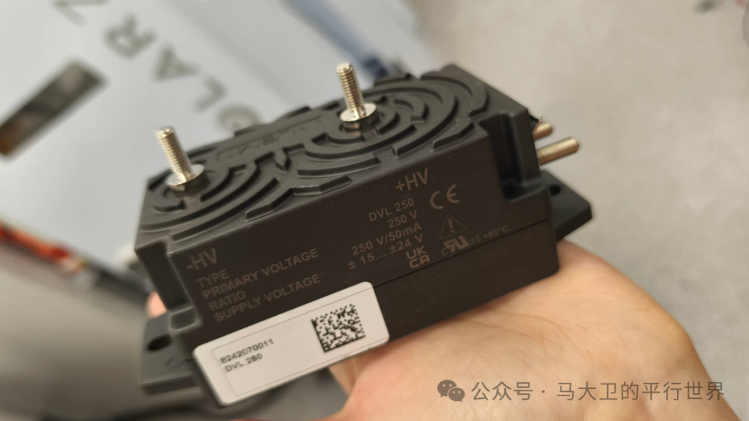
We are using the LEM DVL 250. Although this model is rated for 250V, it can measure bipolar and insulated voltages up to 375V. The two terminals at the top of the image connect to the circuit to be measured, with the right side marked +HV, the complete circular shape is the positive terminal, and the left side -HV with a semicircle is the negative terminal. If connected incorrectly, it won’t cause major issues; the output value will just be reversed.
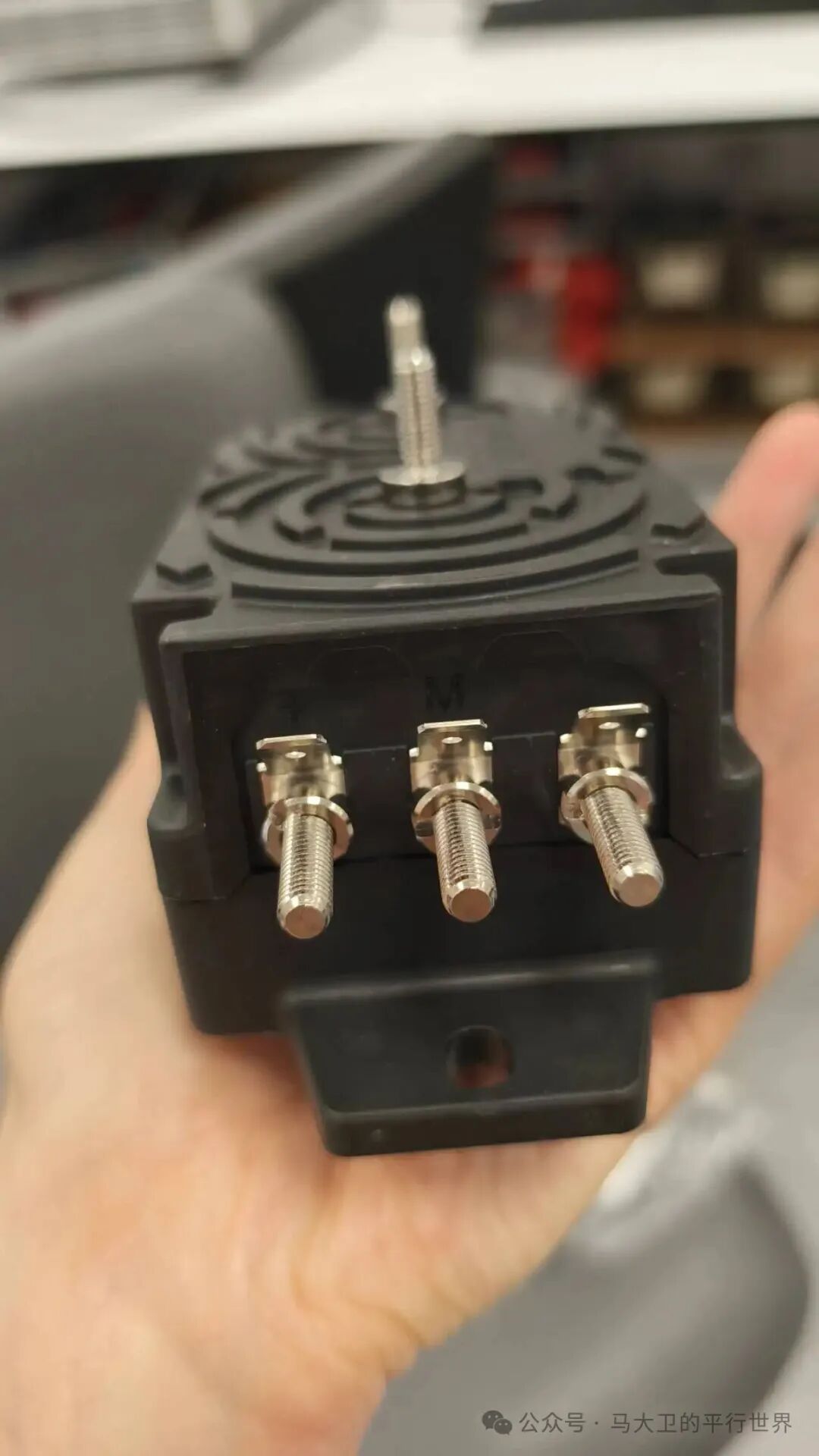
The above image shows three terminals. This voltage sensor is active and requires an external power supply, so the leftmost + terminal and the rightmost – terminal are for power input. The voltage difference should be about 30V, with +15V for the positive terminal and -15V for the negative terminal. I am a spendthrift and provided each sensor with a switching power supply.
The middle M terminal is the output terminal. Pay attention! The output of the DVL is current, so we need to convert it to voltage. A resistor of about 50Ω will suffice. The specific method is as follows:
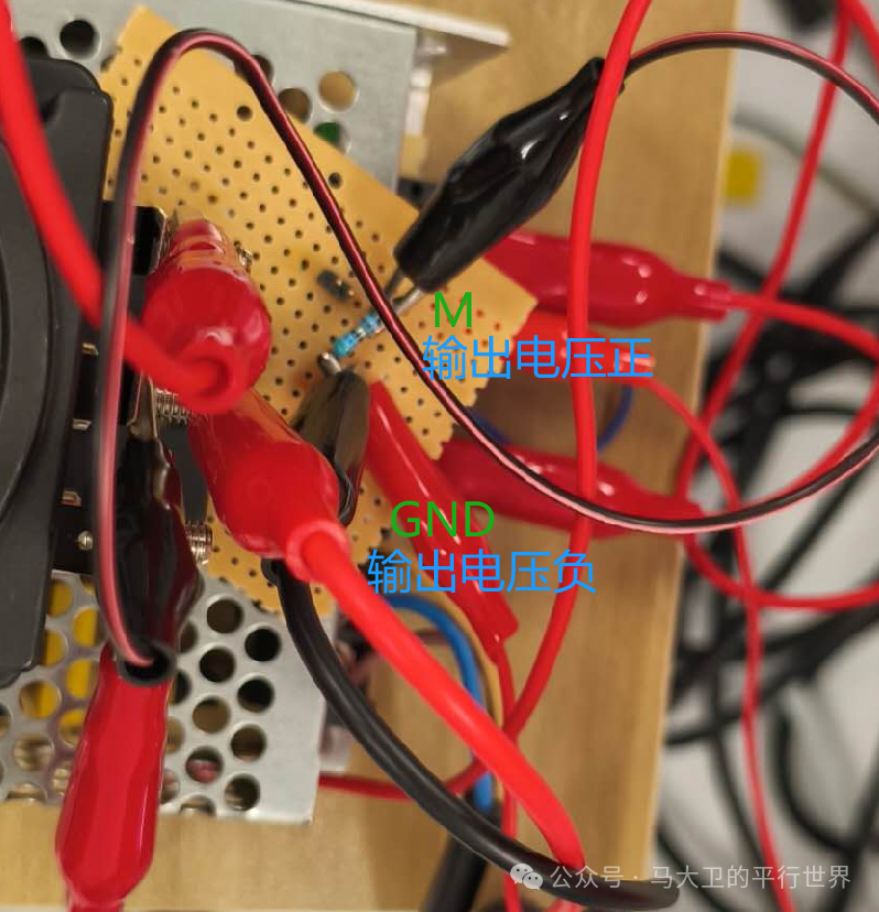
One end of the resistor connects to the M terminal and the positive output, while the other end connects to GND and the negative output. This way, you can output an accurate voltage value.
When reading the voltage, you may find that the displayed value deviates from the actual value. This deviation may be due to the resistor value, range, or scaling issues. We can test multiple sensors to confirm whether all sensors have this problem. If all show the same deviation, we can simply multiply the output result by the corresponding gain factor using a Gain module.This deviation can be identified using a known voltage.
For example, during my experiments, I found that all sensors’ outputs were 1.44 times higher than the actual values. In this case, we can process the results by multiplying by 1/1.44.
! There is also a life-threatening issue. Never, ever adjust the input voltage at the +- terminals while powered on! At that time, I was unsure of the cause of the deviation and wondered if it was due to the switching power supply’s voltage being too high or too low, so I adjusted the output of the switching power supply while the sensor was powered on. I only reduced it from 30V to 25V, and the sensor was fried. So the deviation was not due to the input voltage; I have already stepped on this landmine for you.
Thank you, friends!
Electrical Bird Science Popularization
Barn Owl
June 7, 2025