Sensors can perceive physical quantities such as force, temperature, light, sound, and chemical components, and can convert them into another physical quantity (usually electrical quantities like current or voltage) according to certain rules, or switch the circuit on and off. By converting non-electrical quantities into electrical quantities, measurement, transmission, processing, and control become much easier.
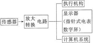
Sensors typically sense non-electrical quantities such as pressure, temperature, displacement, concentration, speed, and pH level, while they output electrical quantities such as voltage, current, and charge. These output signals are very weak and usually need to be amplified before being sent to the control system to generate various control actions. The principle of sensors is illustrated in the figure.
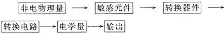
General Mode of Sensor Applications

☞: Photoresistor – Fire Alarm
1.The resistance of the photoresistor changes when illuminated, allowing it to convert the intensity of light into a corresponding electrical quantity (resistance).
2.The resistance of the photoresistor decreases as the light intensity increases.
Photoresistors are typically made from semiconductor materials. When exposed to light or elevated temperatures, more electrons gain energy to become free electrons, creating more holes, thus significantly enhancing conductivity.
☞: Temperature Sensor Application – Electric Iron
Temperature sensors can be made from thermistors or metal thermistors, which can convert thermal signals into electrical signals for automatic control.
(1) Structure of Electric Iron:
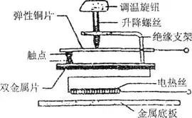
(2) Automatic Temperature Control Principle of Electric Iron: It contains a bimetallic temperature sensor inside, as shown in the figure above.
Under normal temperature, the upper and lower contacts should be in contact, but when the temperature is too high, due to the different thermal expansion coefficients of the bimetallic strip, the upper metal expands more than the lower metal, causing the bimetallic strip to bend downwards, separating the contacts, thus cutting off the power supply and stopping heating. When the temperature decreases, the bimetallic strip returns to its original state, reconnecting the circuit to heat, and this cycle continues, achieving automatic temperature control.
Ironing cotton and linen garments and silk garments requires setting different temperatures. How is this achieved using the temperature control knob?
Under normal temperature, the upper and lower contacts should be in contact. When the temperature is too high, the expansion coefficients of the bimetallic strip differ, with the upper metal having a greater expansion coefficient than the lower metal, causing the upper metal to bend downwards and separate the contacts. The temperature control knob adjusts the lift of the screw to set different temperatures. If a higher temperature is required, the screw should be lowered; conversely, if a lower temperature is needed, it should be raised.
☞: Capacitive Pressure Sensor
When the pressure F to be measured acts on the movable diaphragm electrode, it causes deformation of the diaphragm, resulting in a change in capacitance. If the capacitor is connected in series with a sensitive ammeter and a power supply, forming a closed circuit, when F presses the diaphragm electrode upwards, the capacitance of the capacitor increases. The ammeter will show a reading indicating that the pressure F has changed (as shown in the figure).

In comparison, metal thermistors have good chemical stability and a wide temperature range, while thermistors are more sensitive.
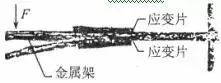
☞: Force Sensor Application – Electronic Scale
(1) Composition: Composed of a metal frame and strain gauges.
(2) Working Principle of Electronic Scale: As shown in the figure, the spring steel beam element is fixed at one end. A strain gauge is attached to the upper and lower surfaces of the beam. When a force F is applied to the free end of the beam, it bends. The upper surface stretches, the lower surface compresses, the resistance of the strain gauge on the upper surface increases, and the resistance on the lower surface decreases. The greater the force F, the greater the bending deformation, and the change in resistance of the strain gauge becomes larger. If the current through the strain gauge is kept constant, the voltage across the strain gauge on the upper surface increases, while the voltage across the strain gauge on the lower surface decreases, with the sensor outputting the voltage difference between these two. The greater the external force, the larger the output voltage difference.
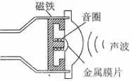
☞: Sound Sensor Application – Microphone
(1) Principle of Dynamic Microphone:
A microphone is a device that converts sound into electrical signals. The following figure shows the structural principle of a dynamic microphone, which is made using the phenomenon of electromagnetic induction. When sound waves cause the metal diaphragm to vibrate, the coil (called the voice coil) connected to the diaphragm also vibrates. The principle diagram of the microphone shows that the voice coil vibrates in the magnetic field of a permanent magnet, generating induced current (electrical signal). The magnitude and direction of the induced current change, with the amplitude and frequency variations determined by the sound wave. This signal current is amplified by an amplifier and sent to a speaker, producing amplified sound.
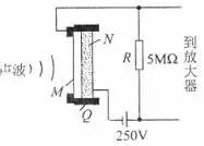
(2) Principle of Capacitive Microphone:
As shown in the figure, Q is the insulating support, and the thin metal film M and the fixed electrode N form a capacitor, charged by a DC power supply. When sound waves cause the diaphragm to vibrate, the capacitance changes, creating a varying current in the circuit, which results in a voltage output across the resistor R that corresponds to the sound variations. Its advantage is good fidelity.
(3) Electret Microphone:
① Polarization Phenomenon: When a dielectric is placed in an electric field, positive and negative charges appear on its front and back surfaces, respectively.
② Electret: Certain dielectrics, after being polarized in an electric field, retain their polarized state after the external electric field is removed. Such materials are called electrets.
③ Principle: Similar to a capacitive microphone, but the sound wave is sensed by a thin electret plastic film inside.
④ Characteristics: Small size, light weight, low cost, high sensitivity, and low operating voltage, requiring only 3-6V.
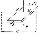
☞: Hall Element
1. As shown in the figure, a conductor plate of thickness d is placed in a uniform magnetic field with magnetic induction strength B perpendicular to it. When a constant current I passes through the conductor plate, a potential difference appears on the left and right sides, a phenomenon known as the Hall effect. By creating four electrodes EFMN on this rectangular semiconductor, it can convert the magnetic induction strength into voltage.
2. Hall Voltage 
① Where k is the proportionality constant, known as the Hall coefficient, which depends on the material of the thin sheet.
② For a Hall element, d and k are constant values, and if I remains constant, then changes proportionally with B, thus the Hall element is also known as a magnetic-sensitive element.
3. Working Principle
The Hall element is designed based on the Hall effect. A rectangular semiconductor sheet has electrodes drawn out at its front, back, left, and right sides. As shown in the figure, when current I flows in the EF direction and a uniform magnetic field B is applied perpendicular to the sheet, a potential difference U appears between MN. Let the thickness of the sheet be d and the length in the EF direction be l1 and in the MN direction be l2. Charged particles in the sheet are deflected by the magnetic force, causing the N side to have a higher potential than the M side, resulting in an electric field inside the semiconductor. The charged particles are also acted upon by the electric field force. When the magnetic force and electric field force balance, the potential difference between MN reaches a constant value.

Based on the microscopic explanation of current
Overall: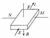
Let where n is the number of charged particles per unit volume of the material, and q is the charge of a single charged particle.
It can be seen that U is proportional to B, which is why the Hall element can convert magnetic quantities into electrical quantities.
▐ Tags: Exam Points Preview, Sensor Working Principles and Applications
▐ For more content, please follow our WeChat public account: Gaokao Physics ID: gkwl100