1. Case Control Requirements
1. Equipment Used: FX3U-PLC (with 485-BD board), Mitsubishi Inverter.
Control Requirements:The PLC communicates with the Mitsubishi E800 inverter to control the inverter’s forward rotation, reverse rotation, and frequency modification.
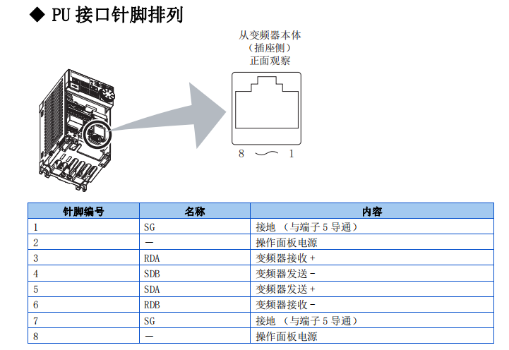
Open the inverter cover, and you will see a port on the circuit board that looks like a network port, but it is actually a 485 communication port. Pins are marked from 1 to 8 from right to left, and we need to connect pins 3, 4, 5, and 6.
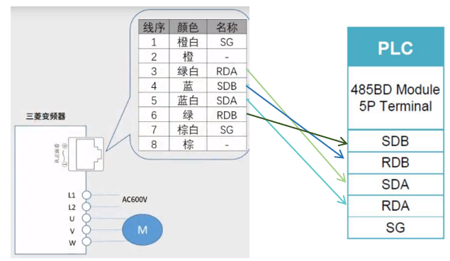
The standard wire color sequence for network cables is orange-white, orange, green-white, blue, blue-white, green, brown-white, brown, so the wiring to the BD board is as follows:
RDA—-SDA, SDB—-RDB, SDA—-RDA, RDB—-SDB
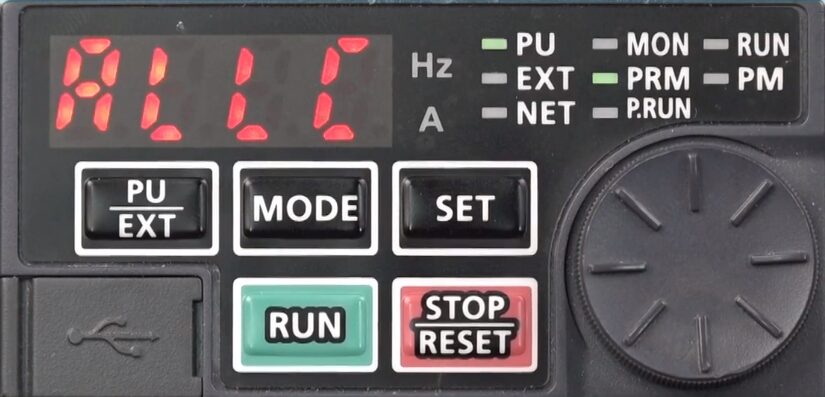
1. Inverter Parameter Settings: Restore the inverter to factory settings: ALLC set to 1.
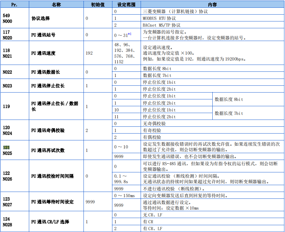
Set communication parameters:
P549 set to 0;
P117 set to 1;
P118 set to 96;
P119 set to 0;
P120 set to 2;
P121 set to 9999;
P122 set to 9999;
P123 set to 9999;
P124 set to 1;
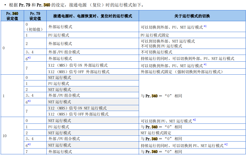
P340 set to 1;
Note: After parameter settings are complete, the inverter needs to be powered off and restarted to take effect.
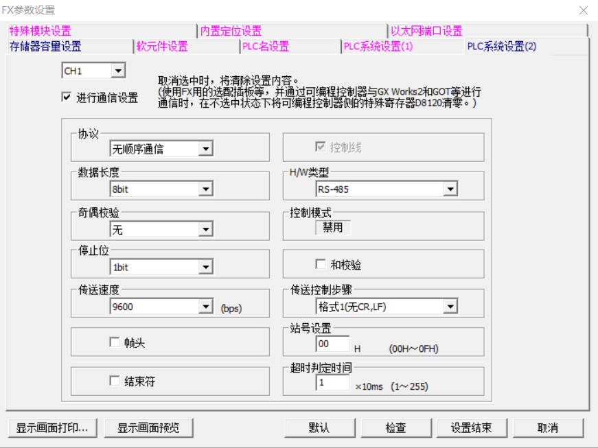
2. PLC Parameter Settings:
For the 3U PLC’s 485 BD board, communication parameters also need to be set. Click on PLC parameters to enter the settings interface. Select PLC system settings 2. Check communication settings for channel 1, with the protocol set to no sequence protocol. Data length, parity, stop bits, and baud rate must be consistent with the inverter parameter settings.
Type, select RS-485. Finally, click to complete the settings.
1. IVDR Instruction: Write data to the corresponding communication address of the inverter.
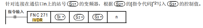
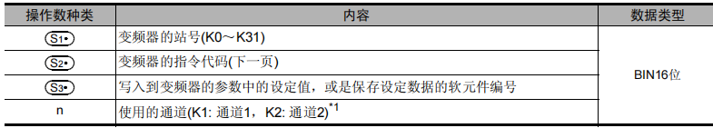
For example, frequency control: Write the set value of D0 into the frequency address of the inverter with station number 1. (Refer to the figure below)

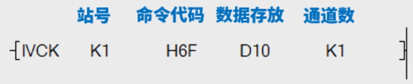
2. IVCK Instruction: Read the corresponding operating status of the inverter and store it.
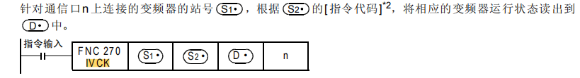
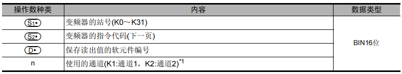
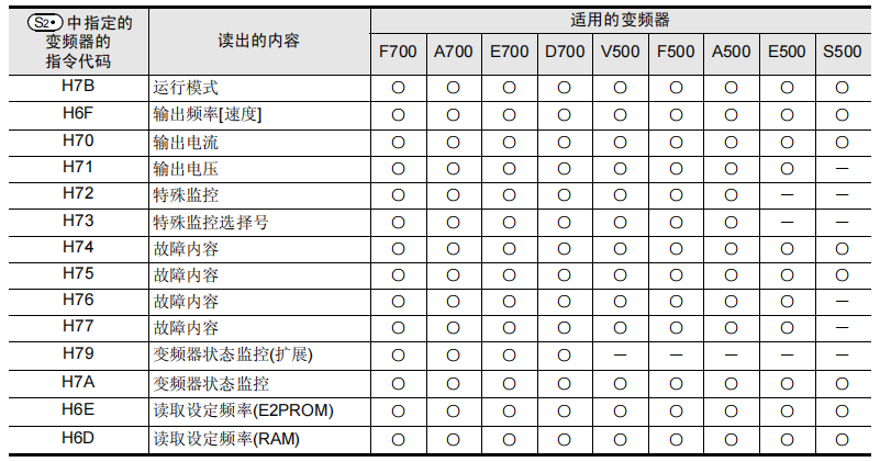
For example, frequency reading: Read the operating frequency of the inverter with station number 1 and store it in D10. (Refer to the figure below)
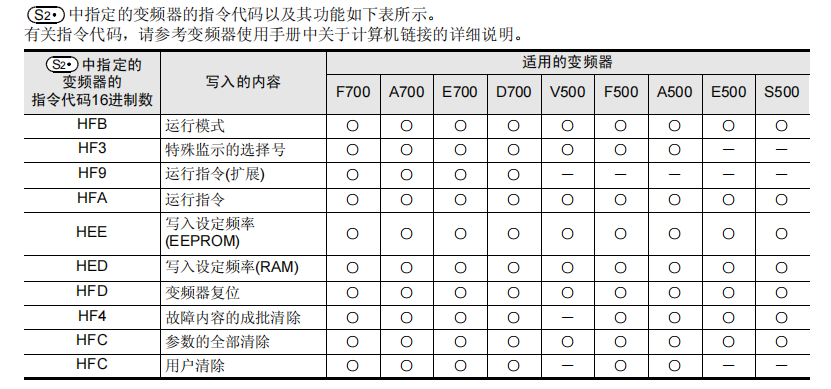
1. By consulting the E800 inverter manual, we can find that:
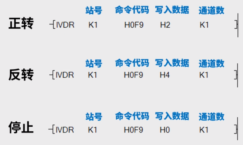
Writing:
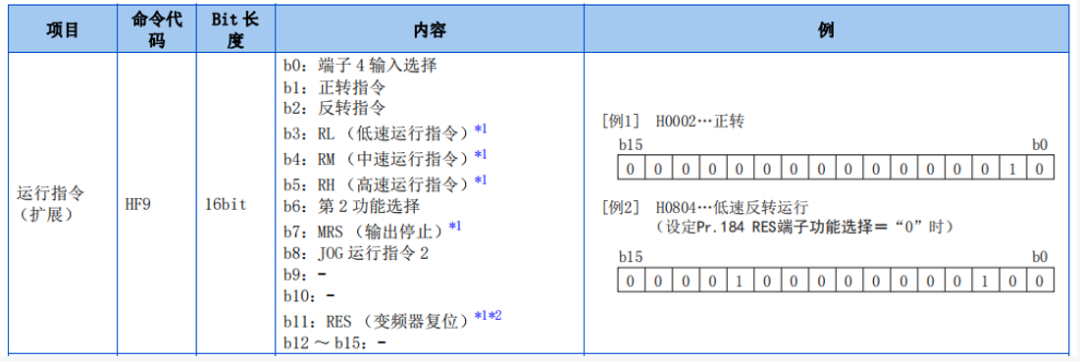
Command code HF9.b1 is the forward command;
Command code HF9.b2 is the reverse command;
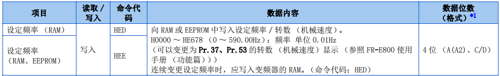
Command codes HED, HEE are for writing frequency;
Note: If the written frequency needs to be maintained after power off, please write using the HEE command code.
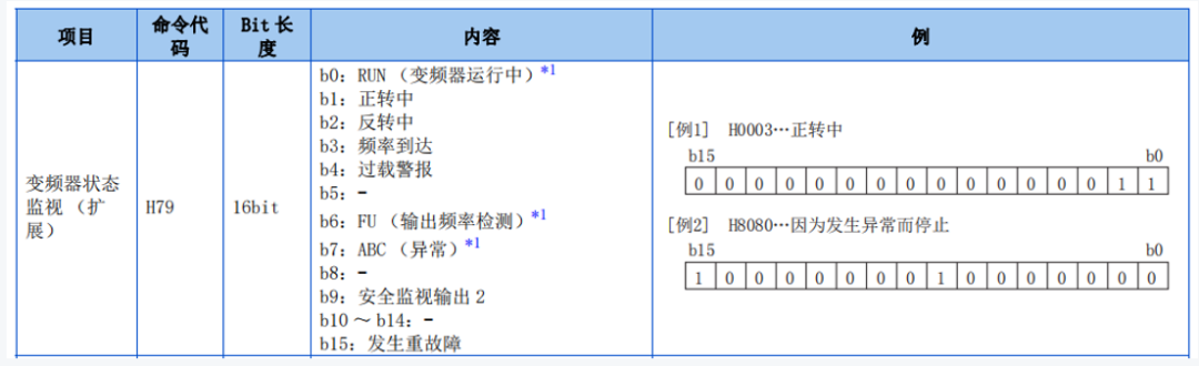
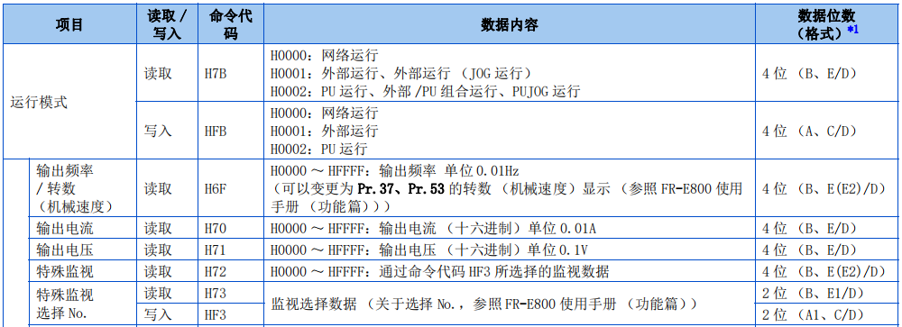
Reading:
Command code H79.b0 indicates the inverter is running;
Command code H79.b1 indicates the inverter is rotating forward;
Command code H79.b2 indicates the inverter is rotating in reverse;
Command code H6F is the inverter’s operating frequency;
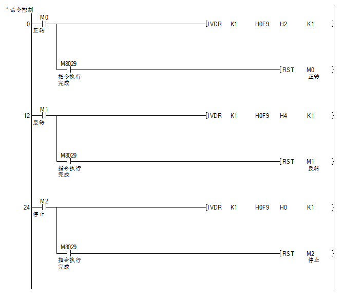
Thus, the command to control the inverter’s operation is:
The command for writing the inverter frequency is:
Note: The inverter frequency has two decimal places, so the actual frequency written must be multiplied by 100.

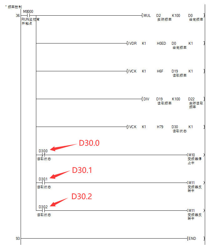
The command for monitoring the inverter’s operating status is:
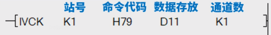
D11.0 indicates the inverter is running, D11.1 indicates the inverter is rotating forward, D11.2 indicates the inverter is rotating in reverse.
The command for monitoring the inverter’s operating frequency is:
Note: The inverter frequency has two decimal places, so the frequency read must be divided by 100.

2. Program Writing:
Note: The instructions discussed in this chapter are specific to Mitsubishi inverters and do not support other brands of inverters. Other inverters can use Modbus RTU communication; refer to the article “FX3U and Mitsubishi E800 Inverter Modbus RTU Communication Application” for details.
Source: Jicheng Training Network, Author: Fan Tengkai, Reproduction without permission is prohibited~


Mitsubishi PLC Complete Documentation Package
Long press the QR code to receive it immediately