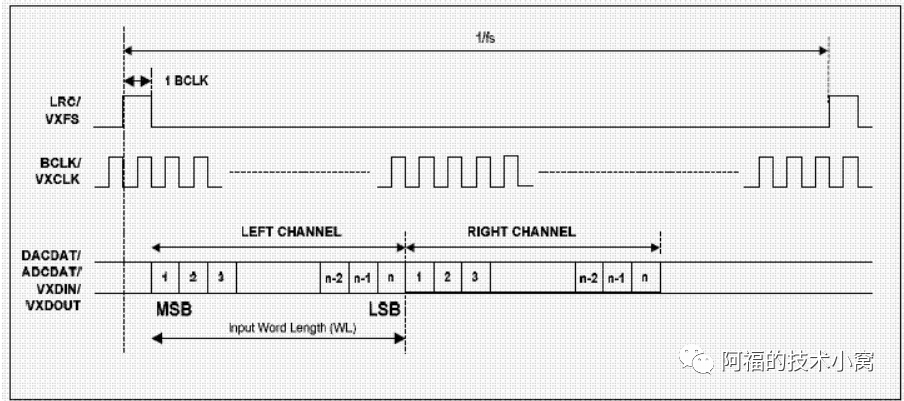
Previously, we introduced I2S. However, we found that I2S has a significant limitation: it can only transmit two channels of audio, left and right. What if I want to transmit 8 channels? 16 channels? Then it becomes impossible!
Let’s imagine a scenario. A car of fixed size has two seats, left and right. We arrange for one person to sit in each seat. Therefore, the car can only transport two people.
If I want to transport more people, what should I do? It’s simple, just squeeze! So, I stuffed four people in. If I want to transport eight people, what should I do? I will find eight thinner people to fit in. Anyway, I will fill the space as much as possible.
Thus, based on I2S, people developed a TDM mode. TDM, also known as Time Division Multiplexing, follows the same principle as the car analogy I mentioned earlier.
The TDM protocol timing is similar to the old version of I2S, but introduces the concept of slots.A slot refers to a frame of data for a specific channel.slot_num refers to the number of slots.slot_width refers to the number of bits in a frame of data.Generally, the number of slots is even, and the number of audio channels should be less than or equal to the number of slots, i.e., channel ≤ slot_num. Similarly, the sampling frequency should be less than or equal to the slot width, fs ≤ slot_width. The timing diagram is as follows:The following diagrams demonstrate TDM transmission for 16 channels, 8 channels, 4 channels, and 2 channels of audio. The transmission frequency of BCLK and SD needs to be increased.
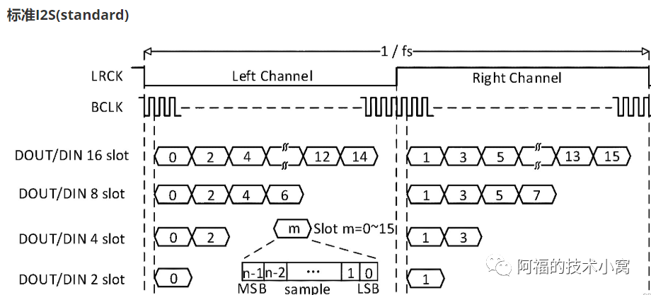
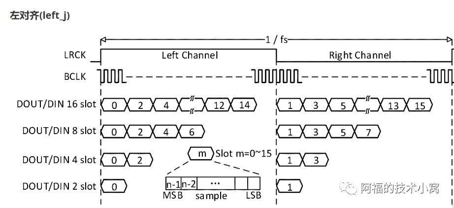
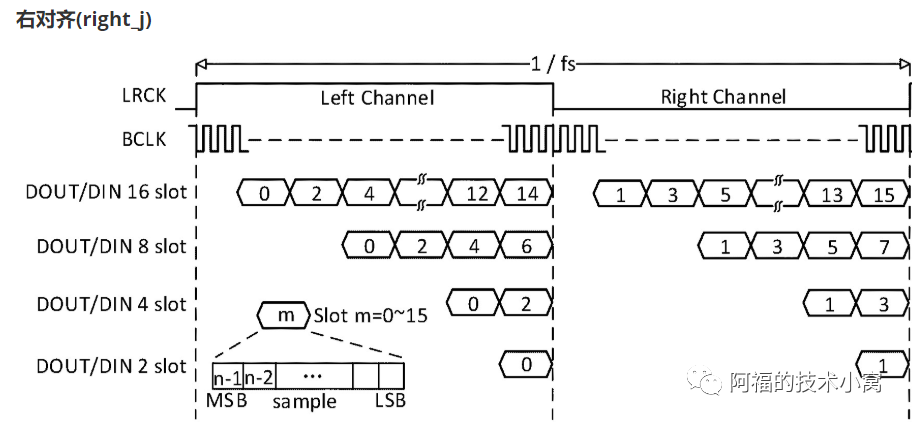
Note: TDM is a variant of I2S, and therefore not standardized; implementations by different chip manufacturers may vary in some aspects.Based on the I2S hardware pins, another variant has emerged, the PCM mode.This PCM is not the audio PCM format we usually refer to. It should be called PCM mode, so do not confuse the two.The PCM interface has the same pins as the I2S interface – frame synchronization clock, bit clock, and mainly has two modes: short frame and long frame.
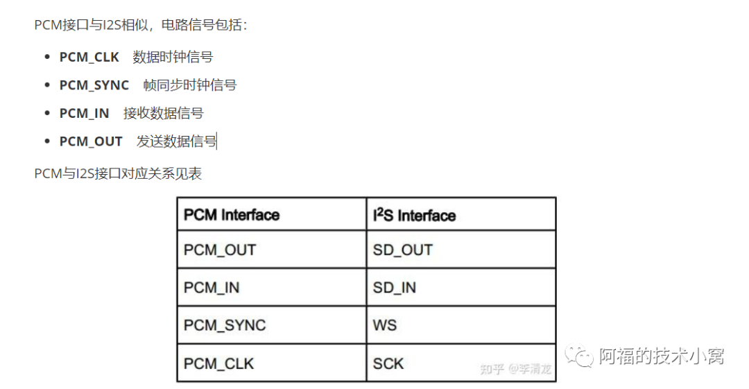
Due to the lack of a unified standard, different manufacturers may have different settings for the FSYNC pulse width and triggering edge.As shown in the figure below: In short frame mode, the frame synchronization clock width is one bit clock cycle, and data is valid on the second rising edge of BCLK after FSYNC is valid; in long frame mode, the frame synchronization clock width is two bit clock cycles, and data is valid on the first rising edge of BCLK after FSYNC is valid.
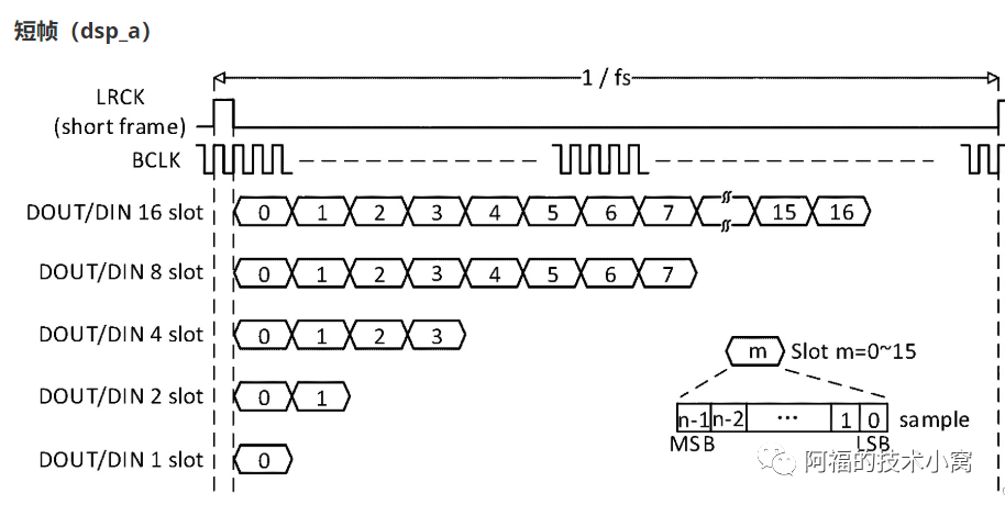
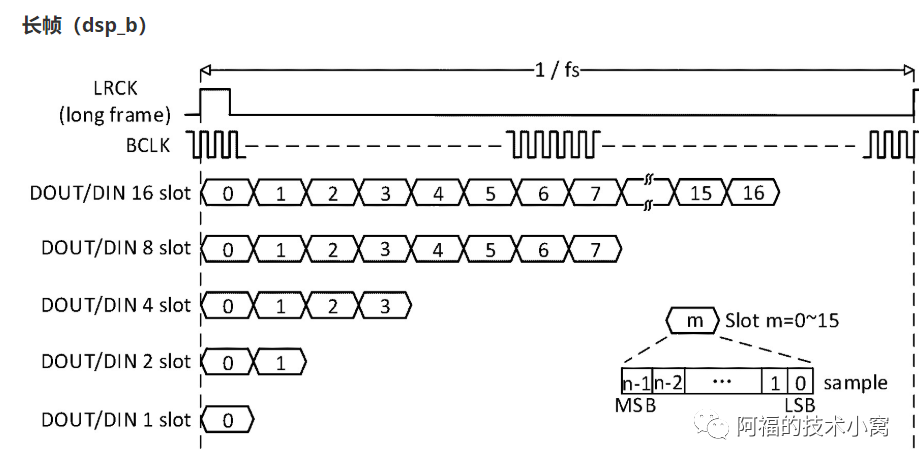
The PCM protocol does not have a unified standard.Finally, let’s make a comparison:From the timing diagrams, we can see that I2S has high and low levels for the left and right channels, while PCM only has one start signal, with left channel data immediately following the right channel.I2S
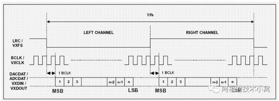
PCM