
This article highlights
The core of PCB layout is “signal flow” and “power flow”. Conventional manual dragging can easily lead to mistakes, making it difficult to find the right placement for components like capacitor R1 among a sea of wires; the quick layout function helps you place components with one click, following certain design rules. It prioritizes grouping electrically connected components together, digitizing and automating the layout experience that veteran engineers often describe as “understandable but not expressible.”✨
In the previous issue, we introduced the via operation in PCBs; this issue will present the quick layout function from the perspective of efficient design, helping engineers digitize their layouts.

Application Scenarios
1. Manually placing decoupling capacitors for a BGA chip with hundreds of pins requires precise alignment with the corresponding power/ground pins nearby. This process is tedious and error-prone; missing one or placing it too far can lead to inexplicable power noise later on. Quick layout automatically completes the “adhesion” of chip capacitors, ensuring efficient layout work.😏
2. High-speed signal currents often require a “return path.” Quick layout concentrates logically related components in the circuit, pre-planning layout areas, thereby reducing EMI risks from the source.🌟

Operating Environment
1. Operating System: Win 11
2. Cadence Software Configuration: Allegro X Designer Plus 24.1-2024 P001 [9/4/2024] Windows SPB 64-bit Edition

Automatic Layout Based on Room Attributes
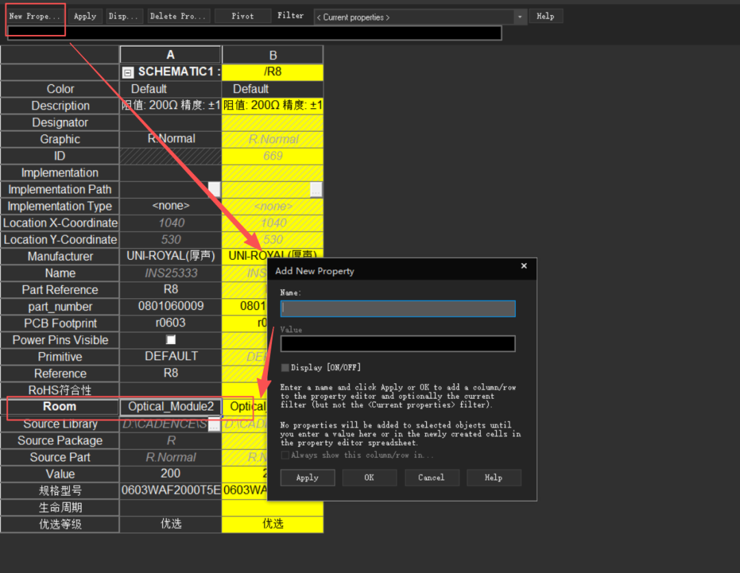
1. Set ROOM attributes
In the OrCAD Capture CIS schematic editor, assign the same Room attribute value to components of a specific module. Select the corresponding components, right-click to Edit Properties, and add the Room attribute value as Optical_Module2.
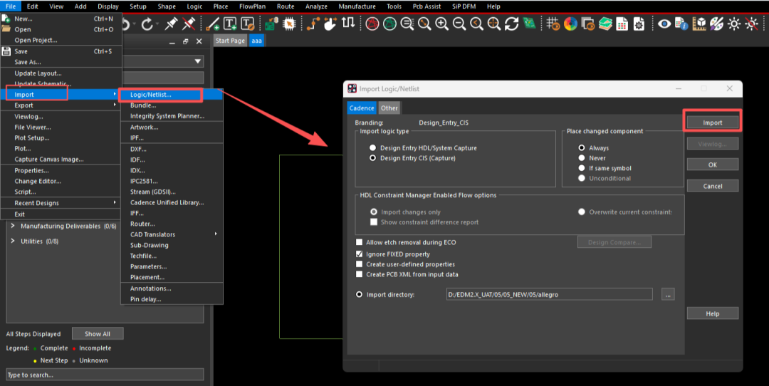
2. Import the schematic netlist containing Room information into the PCB design tool. In OrCAD Capture CIS, execute Tools-Create Netlist to generate the netlist; open Allegro PCB Designer, click File-Import-Logic to import the netlist; select the corresponding file path and click Import.
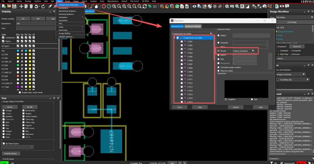
3. Manually Place Components
Select the menu Place-Components Manually to place components. In the Placement component placement interface, on the right side under Selection filters, select Room, and choose one of the Room attribute values; all components assigned with that Room attribute will be filtered on the right side; selecting all allows for continuous placement of components.
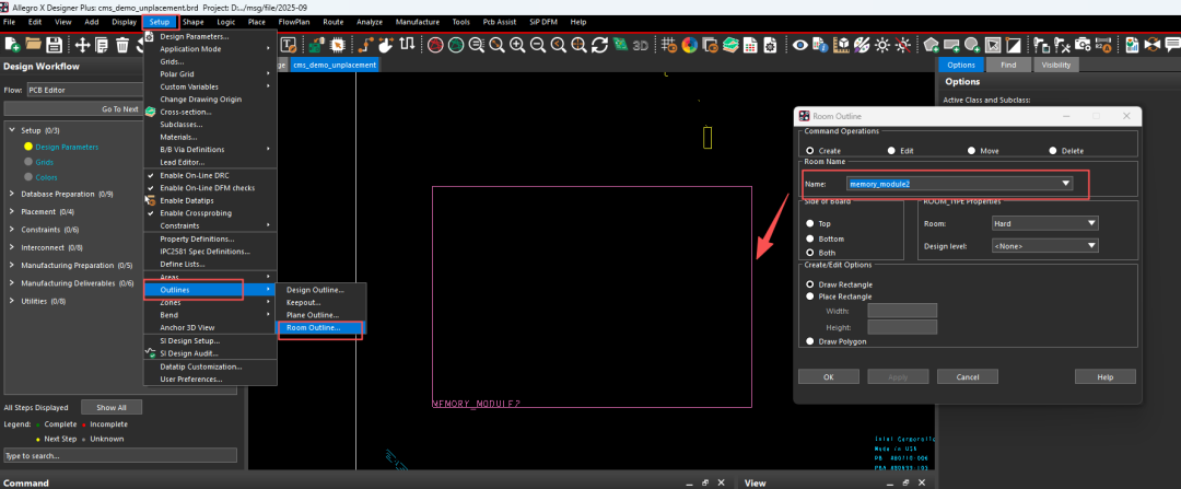
4. Create Room Boundaries in PCB
Once the Room Outline is completed, components can be quickly placed into their corresponding Room or nearby. Select the menu Setup-Outlines-Room Outline, set the Room’s layer position on the board, and whether components must strictly be placed within the Room, then define the area on the board.
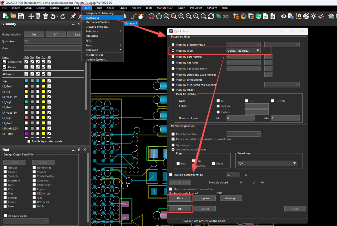
5. Use Quickplace for Automatic Layout
Select the menu Place-Quickplace, choose Place by room, and select a Room attribute value Optical_Module2 from the dropdown. Click Place to perform one-click placement of component attributes.

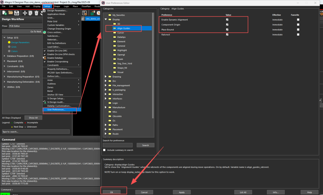
Dynamic Component Alignment
1. The dynamic component alignment feature displays guidance information for component placement, allowing for alignment during component movement. You can configure the starting position and edge position of the components simultaneously. Select the menu Setup-User Preferences-Display-Align Guides; enable Dynamic Alignment, Component Origin, and Place Bound, then click OK.
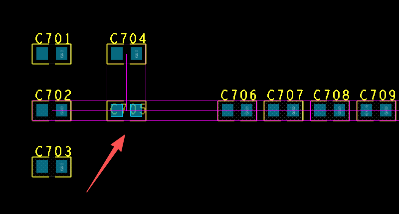
2. When moving capacitor C705 to be directly below C704, some guide lines will appear on the board to help align these components.
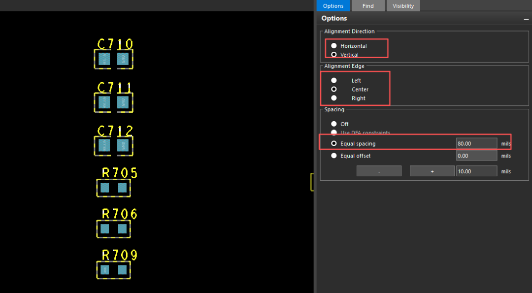
3. Execute the command to align all components; select the group of components that need to be arranged orderly, right-click and choose Align components for one-click alignment of component positions.
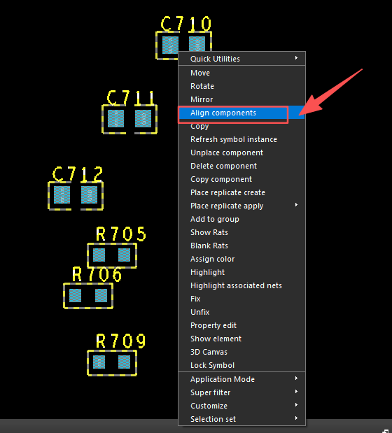
4. After executing the alignment command, you can set the alignment method, center point position, and spacing between components in the right-side Options panel. After setting, right-click and click Done to complete the command.
💬 Summary
This issue mainly introduced the quick layout operation of components. In the next issue, we will explain the 3D model mapping of PCBs and related operations.👋


Click the image to learn more about the product!

END
People who like this content also like
Technical Insights: Via Operations in Allegro PCB Design
Free Download: [E-book] Flexible and Rigid-Flex PCB Design Guide
Technical Insights: Can Data Centers Withstand High-Temperature Operations?
Technical Insights: Routing Optimization in Allegro PCB Design
 We welcome your comments!You can leave a message through the WeChat backend or email us at[email protected]. Thank you very much for your attention and valuable feedback.
Click “Read the original text” to get the product manual for free!
↓↓↓
We look forward to your shares, likes, and views