The MCP41010 is a single-channel digital potentiometer produced by Microchip, supporting SPI interface, with a resistance value of 10kΩ and a resolution of 8 bits (0-255 wiper positions). Below is the complete implementation scheme for driving the MCP41010 via SPI with STM32, as shown in the circuit diagram below.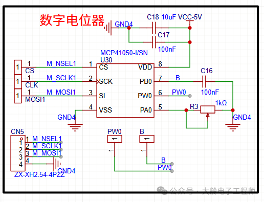
| STM32 Pin | MCP41010 Pin | Function Description |
|---|---|---|
| PA5 | M_SCLK1 | SPI Clock |
| PA7 | M_MOSI1 | SPI Data Input |
| PA4 | M_NSEL1 | Chip Select (active low) |
| VCC | VDD | Power Supply (3.3V) |
| GND | VSS | Ground |
II. Key Points for SPI Configuration
- SPI Mode: CPOL=0, CPHA=0 (SPI Mode 0)
- Data Order: Most Significant Bit First (MSB First)
- Clock Frequency: Maximum supported 10MHz (STM32 can be set to 8MHz)
- Chip Select Control: Software control of CS pin (active low)
III. STM32 Code Implementation (HAL Library)
#include "stm32f1xx_hal.h"
SPI_HandleTypeDef hspi1;

// SPI initialization function
void MX_SPI1_Init(void) {
    hspi1.Instance = SPI1;
    hspi1.Init.Mode = SPI_MODE_MASTER;          // Master mode
    hspi1.Init.Direction = SPI_DIRECTION_1LINE; // Single line transmission
    hspi1.Init.DataSize = SPI_DATASIZE_8BIT;    // 8-bit data
    hspi1.Init.CLKPolarity = SPI_POLARITY_LOW;  // CPOL=0
    hspi1.Init.CLKPhase = SPI_PHASE_1EDGE;      // CPHA=0
    hspi1.Init.NSS = SPI_NSS_SOFT;              // Software NSS
    hspi1.Init.BaudRatePrescaler = SPI_BAUDRATEPRESCALER_2; // 8MHz (72MHz/2)
    hspi1.Init.FirstBit = SPI_FIRSTBIT_MSB;     // Most Significant Bit First
    hspi1.Init.TIMode = SPI_TIMODE_DISABLE;
    hspi1.Init.CRCCalculation = SPI_CRCCALCULATION_DISABLE;
    if (HAL_SPI_Init(&hspi1) != HAL_OK) {
        Error_Handler();
    }
}

// GPIO initialization (CS pin)
void MX_GPIO_Init(void) {
    GPIO_InitTypeDef GPIO_InitStruct = {0};
    __HAL_RCC_GPIOA_CLK_ENABLE();
    // PA4 (CS) configured as push-pull output
    GPIO_InitStruct.Pin = GPIO_PIN_4;
    GPIO_InitStruct.Mode = GPIO_MODE_OUTPUT_PP;
    GPIO_InitStruct.Pull = GPIO_NOPULL;
    GPIO_InitStruct.Speed = GPIO_SPEED_FREQ_HIGH;
    HAL_GPIO_Init(GPIOA, &GPIO_InitStruct);
    // Default CS high (deselected)
    HAL_GPIO_WritePin(GPIOA, GPIO_PIN_4, GPIO_PIN_SET);
}
#define MCP41010_CS_PIN GPIO_PIN_4
#define MCP41010_CS_PORT GPIOA
// Write wiper position (0-255)
void MCP41010_SetWiper(uint8_t value) {
uint8_t tx_data[2];
// Command format: 00010000 + wiper value (MCP41010 command set)
tx_data[0] = 0x10; // Write Wiper 0 command
tx_data[1] = value; // Wiper position (0=min resistance, 255=max resistance)
// Select device
HAL_GPIO_WritePin(MCP41010_CS_PORT, MCP41010_CS_PIN, GPIO_PIN_RESET);
// Send data
HAL_SPI_Transmit(&hspi1, tx_data, 2, 100);
// Deselect
HAL_GPIO_WritePin(MCP41010_CS_PORT, MCP41010_CS_PIN, GPIO_PIN_SET);
}
// Quickly set resistance value (percentage)
void MCP41010_SetResistance(float percent) {
if(percent < 0) percent = 0;
if(percent > 100) percent = 100;
uint8_t value = (uint8_t)(percent * 255 / 100);
MCP41010_SetWiper(value);
}3. Example of Main Function Call
int main(void) {
    HAL_Init();
    SystemClock_Config(); // System clock configuration needs to be implemented
    MX_GPIO_Init();
    MX_SPI1_Init();
    while (1) {
        // Set to 50% resistance (approximately 5kΩ)
        MCP41010_SetResistance(50);
        HAL_Delay(1000);
        // Set to minimum resistance (0Ω)
        MCP41010_SetWiper(0);
        HAL_Delay(1000);
        // Set to maximum resistance (10kΩ)
        MCP41010_SetWiper(255);
        HAL_Delay(1000);
    }
}
IV. Key Considerations
- SPI Timing Match: The MCP41010 requires the SPI clock frequency not to exceed 10MHz; ensure the prescaler is set correctly when configuring STM32.
- Power Supply Stability: The VDD of the MCP41010 must match the IO level of the STM32 (3.3V) to avoid level mismatch.
- Command Format: The command byte for the MCP41010 is
<span>0x10</span>(write Wiper 0), which should not be modified arbitrarily (refer to the data sheet Table-5-1). - Hardware Decoupling: Place a 0.1μF capacitor in parallel next to the VDD pin of the MCP41010 to enhance power stability.
- Wiper Value Range: 0 corresponds to minimum resistance (wiper connected to the lower terminal), 255 corresponds to maximum resistance (wiper connected to the upper terminal).
V. Troubleshooting
- No Response: Check if the CS pin is correctly pulled low, if the SPI clock is outputting, and if the data line connections are correct.
- Abnormal Resistance Value: Confirm that the command byte is
<span>0x10</span>and that the wiper value is within the range of 0-255. - SPI Communication Error: Use a logic analyzer to check the SPI timing and ensure CPOL/CPHA is configured for mode 0.
With the above code and configuration, the STM32 can stably drive the MCP41010 to achieve the function of adjusting the resistance of the digital potentiometer. To read the current wiper value, refer to the read operation instructions in the MCP41010 data sheet to extend the code.