Objectively speaking, COG、COF、COP are three different packaging technologies for display driver chips in screens, commonly referred to as ‘screen packaging’ in the media. The main application of the three is to achieve the driving control of screens (LCD,OLED) by mobile or television systems, as well as signal connections with other systems such as the mainboard FPCB and components. COG = Chip On Glass (literally: chip on top of glass). It directly bonds the mobile screen display driver chip (Display Driver IC, DDIC) to a rigid glass substrate (Glass Substrate), which is then linked to the rest of the mobile PCB or components by FPCB. This is typically used for rigid displays, such as LCD. See Figure 1.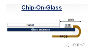 Figure 1: COG Cross-Section Diagram COF = Chip On Film (literally: chip on top of film). It indirectly bonds the DDIC to a flexible plastic substrate (Plastic Substrate) through an adhesive thin film (Adhesive Thin Film) to achieve flexible displays (such as OLED). See Figure 2.
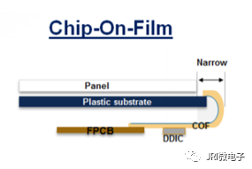 Figure 2: COF Cross-Section Diagram COP = Chip On Plastic (literally: chip on top of plastic). It directly fixes the DDIC onto a flexible plastic substrate (Plastic Substrate). See Figure 3.
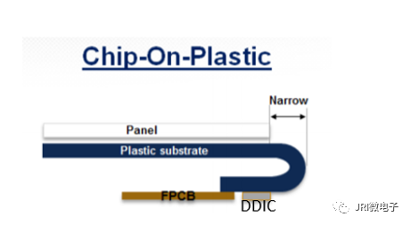 Figure 3: COP Cross-Section DiagramCOF and COP’s flexibility allows the side areas of the screen (the borders) to be designed narrower. This results in a relatively large screen-to-body ratio, achieving a ‘borderless’ or ‘full-screen display’. To accommodate the bending flexibility of OLED flexible screens, the packaging of the DDIC chip must also be based on flexible materials. This is why COF and COP technologies must be applied. In contrast, the rigid DDIC chip packaging based on COG (Figure 1) cannot achieve folding or bending. For example, the iPhone 7 screen uses a COG-based LCD, see Figure 4; starting with iPhone 10, Apple uses a COF-based OLED screen, see Figure 5.
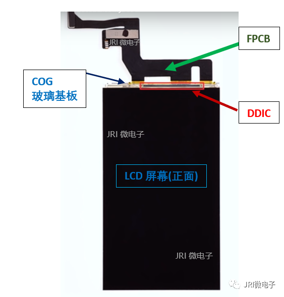
Figure 4: COG LCD screen, iPhone 7
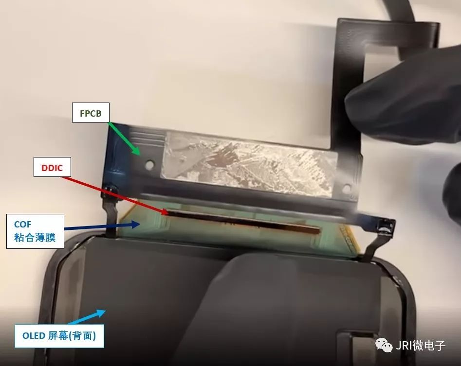
Figure 5: COF OLED screen analysis, iPhone X
Both COF and COP are used for the packaging of flexible screens OLED, with the difference being the indirect and direct connection of the DDIC (Figures 2 and 3). In fact, the DDIC in COF links the screen and the mainboard FPCB through an adhesive film, indicating that COF is not as flexible as COP. In COP, the DDIC is directly fixed onto the flexible plastic substrate of COP, forming a whole (Figure 3), which allows the plastic flexible substrate of COP to bend without physical constraints at the edge of mobile phones or televisions (Edge Curved), further reducing the border to achieve an almost borderless effect. COP is a brand new screen packaging technology, first debuted in Samsung S8, and OPPO Find X is the second phone to adopt this screen packaging technology.
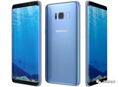
Figure 5: Samsung S8’s (almost) borderless OLED screen
Today, we introduced the technical foundations of COG, COF, and COP, hoping it can be helpful to everyone in their work and life. Original technical articles are not easy to create, and the research institute continuously publishes original technical explanations in related disciplines, please pay attention to the research institute’s WeChat account [JRI Microelectronics].Wishing all colleagues “learn the way and apply what you learn”!
Previous related reports:
-
Antenna’s PCB Integrated Packaging Structure AiP
-
100 PCB Terminology Explained, No More Interview Fears
-
Your Next Mobile Phone Memory Starts at 166 GB!
-
Intel Technology Strategy Part I
-
Intel Technology Strategy Part 2
-
Intel Technology Strategy Part 3
-
The World’s First Extreme Ultraviolet EUV 7nm Chip Huawei Kirin 985
-
Samsung: Starting Design of 3nm Chips, Trial Production Next Year!
-
[2 Minutes] Understand the Current Status of 5nm Chip Technology Development
The above article is from the CPCA-TUD Microelectronics Joint Research Institute (JRI)
The research institute is affiliated with the China Printed Circuit Association (CPCA)
Please pay attention to the research institute’s WeChat account 【JRI Microelectronics】
Long press to identify the QR code to follow 【JRI Microelectronics】

-End-